Hand-operated starter and mini-tiller
A starter and hand-operated technology, applied in the field of hand-operated starters, can solve the problems of increased use cost, starter failure, short service life, etc., and achieve the effects of fast start-up speed, high start-up efficiency and long service life
- Summary
- Abstract
- Description
- Claims
- Application Information
AI Technical Summary
Problems solved by technology
Method used
Image
Examples
Embodiment 1
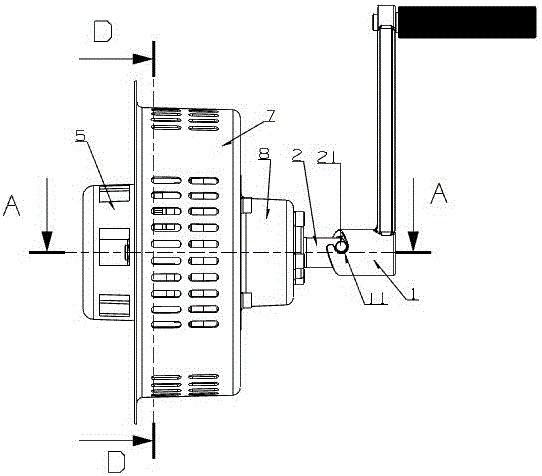
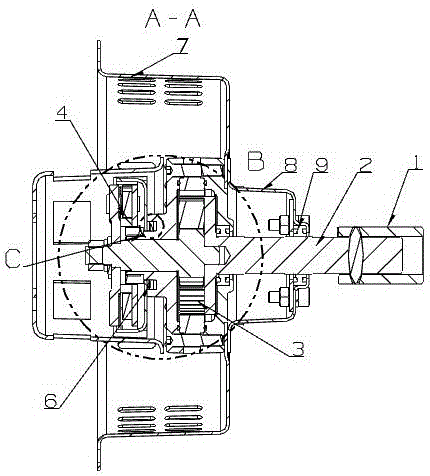
[0042] Embodiment 1: as Figure 1-3 As shown, a hand starter includes a rocker arm 1 and a rocker shaft 2 connected to the rocker arm 1, the rocker shaft 2 is connected to a speed-up mechanism 3, and the speed-up mechanism 3 is connected to a throwing block The mechanism 4 is connected, and the described block mechanism 4 drives the starting cup 5 of the engine.
[0043] Using the manual starter of this embodiment, the rocker arm 1 is manually shaken to make the rocker arm shaft 2 rotate, and the rocker arm shaft 2 drives the speed-up mechanism 3 to rotate and achieve the effect of speed-up through the speed-up mechanism 3, and then The speed-up mechanism 3 drives the block-throwing mechanism 4 to rotate, and the block-throwing mechanism 4 drives the starting cup 5 of the engine to rotate through the block. After the engine starts, the starting cup will continue to rotate and drive the block to rotate , at this time the manual shaking can be stopped, and the engine has been s...
Embodiment 2
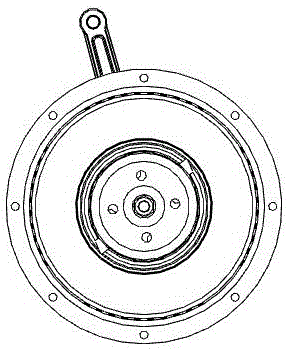
[0046] Embodiment 2: as Figure 1-5 As shown, a hand starter includes a rocker arm 1 and a rocker shaft 2 connected to the rocker arm 1, the rocker shaft 2 is connected to a speed-up mechanism 3, and the speed-up mechanism 3 is connected to a throwing block The mechanism is connected with 4, and the described block throwing mechanism 4 drives the starting cup 5 of the engine.
[0047] Wherein, the speed-up mechanism 3 includes a planetary gear 31 , the rocker shaft 2 is connected with the planet carrier 32 of the planetary gear 31 , and the sun gear 33 of the planetary gear 31 is connected with the block throwing mechanism 4 . The block throwing mechanism 4 includes an outer casing 41 , and a block throwing part is arranged inside the outer casing 41 . The throwing block part includes a top wall 42 and a bottom wall 43 arranged in the outer casing 41, a support column 46 is arranged between the top wall 42 and the bottom wall 43, and the throwing block 44 is rotatably sleeved...
Embodiment 3
[0052] Embodiment 3: as Figure 1-5 As shown, this embodiment is an improvement on the basis of Embodiment 2. In this embodiment, a frictional pre-tightening force mechanism 6 is also provided between the speed increasing mechanism 3 and the block throwing mechanism 4 .
[0053] Wherein, the speed-up mechanism 3 also includes a top case 34 and a bottom case 35 arranged on both sides of the planetary gear 31, the top case 34, the ring gear of the planetary gear 31 and the bottom case 35 are connected by screws. The bottom shell 35 is sleeved on the rocker shaft 2 through a bearing, and the top shell 34 is sleeved on the gear shaft. An accommodating cavity for accommodating the friction pre-tightening force mechanism 6 is provided on the end wall of the top shell 34 . In this embodiment, the accommodating cavity is set as follows: in the middle of the end of the top case 34, a convex portion extending along the gear shaft is provided, and the convex portion is connected to the ...
PUM
 Abstract
Description
Claims
Application Information
 - R&D
- Intellectual Property
- Life Sciences
- Materials
- Tech Scout
- Unparalleled Data Quality
- Higher Quality Content
- 60% Fewer Hallucinations
Browse by: Latest US Patents, China's latest patents, Technical Efficacy Thesaurus, Application Domain, Technology Topic, Popular Technical Reports.
© 2025 PatSnap. All rights reserved.Legal|Privacy policy|Modern Slavery Act Transparency Statement|Sitemap|About US| Contact US: help@patsnap.com


