Multi-cavity fluid power diaphragm pump system

A fluid power, diaphragm pump technology, applied in the components of pumping devices for elastic fluids, liquid fuel engines, pumps, etc., can solve problems such as increasing starting pressure, increasing diaphragm strength, and short life

Active Publication Date: 2017-05-31
JIANGSU SUZHONG PUMP MFG CO LTD
View PDF12 Cites 4 Cited by
  • Summary
  • Abstract
  • Description
  • Claims
  • Application Information

AI Technical Summary

Problems solved by technology

Its disadvantages: (1) When one working chamber is inflated, the other working chamber is deflated synchronously, the pressure of the inflated chamber is gradually increasing, and the pressure of the deflated chamber is gradually decreasing, because the linkage rod connects the two diaphragms in the At the same time, the residual pressure of the deflation chamber during the deflation process will generate a back pressure on the diaphragm of the deflation chamber, and act on the diaphragm of the other inflating chamber through the linkage rod to form a reaction force, thereby improving the The starting pressure affects the operating efficiency of the pump
(2) The installation of the linkage rod and the installation position of the signal valve or pilot valve make it impossible for the two single-acting diaphragm pumps that make up the diaphragm pump to be installed separately or stacked in series or compactly installed side by side to adapt to the installation environment and conditions of the pump. , for example to accommodate the small diameter problem
(3) The open structure located at the junction of the inner wall of the pump casing delivery chamber and the inlet and outlet valves, because there is no pressure support, the diaphragm is easily damaged when it is empty or lightly loaded; or in order to prevent the diaphragm from being damaged and ruptured, The strength of the diaphragm must be increased, thereby increasing the starting pressure and affecting the operating efficiency of the pump
(4) Since the shell and diaphragm of the working chamber are not insulated, when the fluid power source is thermal power, the pump will generate a large amount of heat dissipation, which will affect the operating efficiency of the pump
(5) The exhaust steam discharged from the pump system not only fails to utilize the remaining pressure, but also causes noise pollution
[0004] In addition, the applicant's Chinese patent authorization announcement number is "pneumatic liquid pump" CN1036089C, "pneumatic pump" with Chinese patent authorization announcement number CN1069953C and "multipurpose thermal machinery" with Chinese patent authorization announcement number CN102538296B. If there is no diaphragm between the working chamber and the conveying chamber, the efficiency is low, and the signal valve is a float type or a magnetic control switch type; The heat-insulating and anti-bending structure results in short pump life and low efficiency

Method used


Image

  • Multi-cavity fluid power diaphragm pump system
  • Multi-cavity fluid power diaphragm pump system
  • Multi-cavity fluid power diaphragm pump system

Examples


no. 1 example

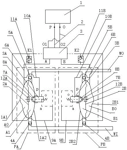
[0050] The first embodiment, with figure 1 It is a system diagram of an air-controlled multi-chamber fluid dynamic diaphragm pump with the delivery chamber close to the inner side and the signal valve installed separately. It consists of paired single-acting diaphragm pumps PA, PB, pneumatic directional control valve 3, Unicom pipeline 2, air compressor 1, etc.; each single-acting diaphragm pump includes pump housings 1A1, 1A2 (2B1, 2B2), and the The working medium and the conveying medium are separated to form the corresponding working chamber AO (BO) and the diaphragm or piston 2A (2B) of the conveying chamber A1 (B1), and the direct-acting one-way machine-controlled fluid pressure signal valve installed on the conveying chamber 3A (3B), feed check valve 4A (4B), discharge check valve 5A (5B), inlet and outlet flow pipe 6A (6B) installed on the working chamber AO (BO), installed in the delivery chamber A1 (B1 ) on the inner wall of the pump housing and sleeved on the trigge...

no. 2 example

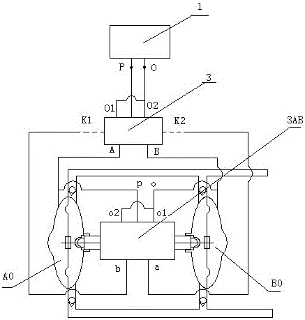
[0053] second embodiment, figure 2 It is a system diagram of an air-controlled multi-chamber hydrodynamic diaphragm pump with the conveying chamber close to the inner side and the signal valve integrally installed in the present invention, figure 2 and figure 1 The main difference between them is the pilot signal valve 3AB and its connection relationship. Pilot signal valve 3AB is a two-position five-way pilot valve with two-position mechanical control. image 3 The A port of the directional control valve 3 is connected with the working chamber AO, and the B port is connected with the working chamber BO; the A port of the directional control valve 3 is also connected with the p port of the pilot signal valve 3AB, and the B port is also connected with the pilot signal valve 3AB. After o1 and o2 are connected, the o port is connected; the b port of the pilot signal valve 3AB is connected with the control port K1 of the directional control valve 3, and the a port of the pilot...


PUM


Abstract

The invention provides a diaphragm pump system with liquid or gas as power. The system comprises single-acting diaphragm pumps pairwise arranged, a direction control valve, a communicating pipeline, a fluid power source and the like; each single-acting diaphragm pump includes a pump shell, a diaphragm or piston for separating a working medium from a conveying medium to form corresponding working cavity and conveying cavity, a signal valve, a feed one-way valve and a discharge one-way valve mounted on the conveying cavity, a flow inlet/outlet pipe mounted on the working cavity, an anti-leakage isolation diaphragm mounted on the inner side wall of the pump shell of the conveying cavity and sleeved out of a signal valve trigger piece and the like; the trigger pieces of signal valves are inserted in the inner sides of the pump shells of the conveying cavities; and control signals output by all the signal valves are communicated with corresponding control ends of the direction control valve. The system is used for conveying various materials, can realize utilization of residual pressure and reduction of the noise, eliminates the back pressure resistance, reduces the starting pressure, improves the pump operation efficiency and the like.

Description

technical field [0001] The invention belongs to the field of thermal power and fluid machinery, in particular to a diaphragm pump system powered by liquid or gas. Background technique [0002] The existing pneumatic diaphragm pump is a new type of fluid machinery powered by compressed air. According to the different materials of the pump casing and diaphragm, it can transport various fluids, especially suitable for transporting various corrosive fluids, fluids with particles, high viscosity, Volatile, flammable and explosive fluids, etc. [0003] Existing pneumatic diaphragm pumps, for example: a pneumatic diaphragm pump with application number 201520349898.3, a pneumatic diaphragm pump with application number 201210132957.2, a pneumatic diaphragm pump with generator with application number CN201080020329.4, application number 201210004322.4 Multi-cavity connected pressurized pneumatic diaphragm pumps, etc., all adopt the following structure: the working chambers of each pa...

Claims


Application Information

Patent Timeline
Patent Type & Authority Applications(China)
IPC IPC(8): F04B43/073F04B53/10F04B53/00
CPCF04B43/0733F04B53/00F04B53/10
Inventor 王政玉王超颖岑陈张玉芹
Owner JIANGSU SUZHONG PUMP MFG CO LTD
Why Eureka
Try Eureka