
Automobile lamp assembly and manufacturing method thereof

A manufacturing method and a technology of car lights, which are applied in the direction of headlights, vehicle parts, motor vehicles, etc., can solve the problems of poor practicability, slow fog dispersing time, poor anti-fog effect car lights, etc., and achieve good intelligence Effect

Inactive Publication Date: 2017-05-31
HENAN POLYTECHNIC
View PDF4 Cites 8 Cited by
  • Summary
  • Abstract
  • Description
  • Claims
  • Application Information

AI Technical Summary

Problems solved by technology

[0005] The object of the present invention is to provide a car lamp assembly and its manufacturing method, so as to reduce the poor effect of the car lamp anti-fog treatment in the prior art, such as poor practicability, poor anti-fog effect and fog inside the car lamp. Slow technical issues

Method used


Image

  • Automobile lamp assembly and manufacturing method thereof
  • Automobile lamp assembly and manufacturing method thereof
  • Automobile lamp assembly and manufacturing method thereof

Examples


Embodiment 1

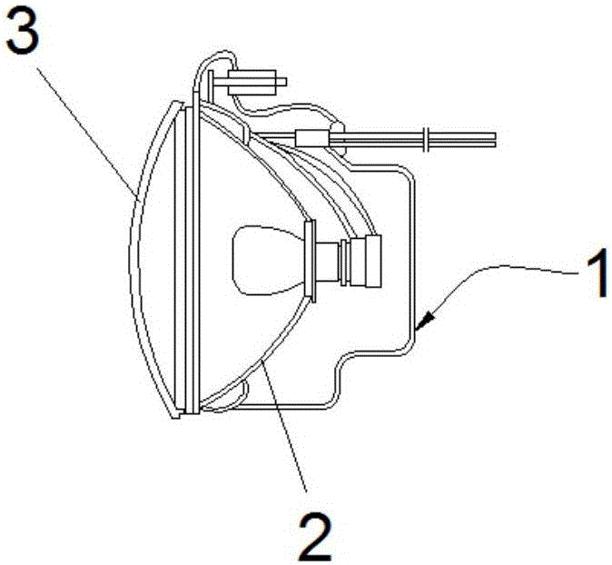
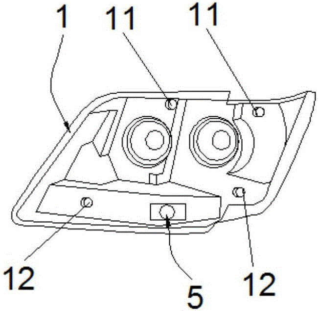
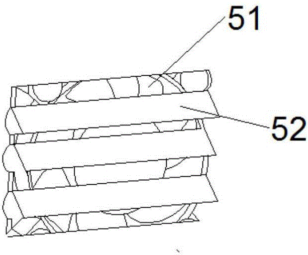
[0038] Such as figure 1 and figure 2 As shown, this embodiment provides a car lamp assembly, including a lamp housing 1, a reflector 2, a humidity sensor 4, a blower device 5, a controller 6, a car lamp and a light distribution mirror 3 connected to the lamp housing 1, A housing cavity is formed between the lamp housing 1 and the light distribution mirror 3, and the reflector 2, the humidity sensor 4, the blower device 5, the controller 6 and the car lights are all located in the housing cavity, and the reflector 2, the humidity sensor 4, the drum The wind device 5 , the controller 6 and the vehicle lamp are all fixed on the lamp housing 1 , and the humidity sensor 4 and the blower device 5 are electrically connected to the controller 6 .

[0039] When the automobile starts, the humidity sensor 4 arranged on the lamp housing 1 can accurately detect the humidity in the lamp assembly. When the humidity in the lamp assembly is higher than or equal to the set value of the humidi...

Embodiment 2

[0053] The present invention also provides a method for manufacturing the above-mentioned vehicle lamp assembly, comprising the following steps:

[0054] a. Sputter a layer of zinc oxide film on the inner surface of the clean reflector 2; for example: put the body of the clean reflector 2 into the sputtering chamber, and spray it on the inner surface of the clean reflector 2 Sputter a layer of zinc oxide film.

[0055] b. Open the exhaust hole 11 and the suction hole 12 on the lamp housing 1, and install the humidity sensor 4, the controller 6, the blowing device 5 and the heating device 7 on the lamp housing 1.

[0056] c. A connection groove for installing the light distribution mirror 3 is opened on the lamp housing 1, and the light distribution mirror 3 is clamped in the connection groove, and then glue is injected into the connection groove and solidified.

[0057] Compared with the prior art, the advantages of the automobile and the above-mentioned lamp assembly are the...


PUM


Abstract

The invention provides an automobile lamp assembly and a manufacturing method thereof, and relates to the technical field of automobile lamps. The automobile lamp assembly comprises a lamp shell, a light reflecting lens, a humidity sensor, a blower device, a controller, an automobile lamp and a lens connected to the lamp shell. A containing cavity is formed between the lamp shell and the lens. The light reflecting lens, the humidity sensor, the blower device, the controller and the automobile lamp are all located in the containing cavity, and the light reflecting lens, the humidity sensor, the blower device, the controller and the automobile lamp are all fixedly arranged on the lamp shell. The humidity sensor and the blower device are electrically connected with the controller. According to the automobile lamp assembly and the manufacturing method thereof, the technical problems that in the prior art, the effect of anti-fog treatment of an automobile lamp is poor, practicability is low, the anti-fog effect is poor, and the dissipating time of fog in the automobile lamp is long are reduced.

Description

technical field [0001] The invention relates to the technical field of vehicle lights, in particular to a vehicle light assembly and a manufacturing method thereof. Background technique [0002] With the development of science and technology and the acceleration of the pace of life, automobiles have become an important means of transportation in people's lives. Among them, as an important lighting component of automobiles, car lights not only play the role of beautiful decoration, but also ensure the safety of motor vehicles at night. Or the safety of driving in weather such as fog and haze. [0003] However, the problem of fogging of headlights has been bothering drivers. As the headlights are turned on, the temperature around the headlights will be higher and higher, and the temperature of the surrounding air will be higher and higher. The temperature of the air at the corners is low, and as the hot air meets the cold air, a layer of water mist is easily formed on the sur...

Claims


Application Information

Patent Timeline
IPC IPC(8): F21S8/10F21V7/22F21V17/16F21V23/04F21V29/67F21V29/83F21V29/90F21V31/00F21W101/02F21W101/10F21W107/10
CPCF21S41/37F21S45/33F21S45/43F21S45/60F21V17/164F21V23/0442F21V29/83F21W2102/00F21W2107/10
Inventor 阴丽华李丽何莉
Owner HENAN POLYTECHNIC
Learn More