Automatic slag removal structure of biomass particle fireplace

A technology of biomass granules and automatic slag removal, applied in lighting and heating equipment, etc., can solve problems such as difficult promotion and application, unusable fireplaces, and large restrictions

Pending Publication Date: 2017-05-31
HENAN SHENHOU IND CO LTD
View PDF14 Cites 7 Cited by
  • Summary
  • Abstract
  • Description
  • Claims
  • Application Information

AI Technical Summary

Problems solved by technology

For biomass particles with large ash content and easy slagging during combustion, the existing fireplace cannot be used
[0004] In order to solve this problem, China has been exploring reasonable technical solutions: some set u

Method used


Image

  • Automatic slag removal structure of biomass particle fireplace
  • Automatic slag removal structure of biomass particle fireplace
  • Automatic slag removal structure of biomass particle fireplace

Examples


Embodiment 1

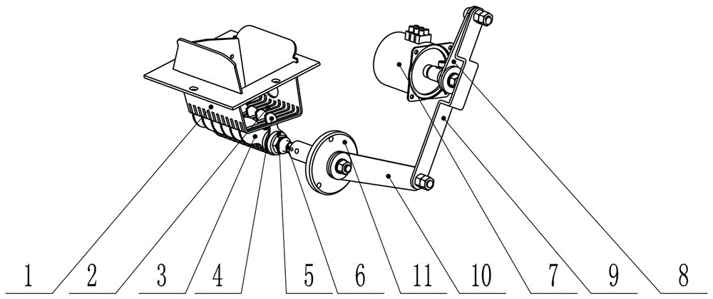
[0033] Such as figure 1 with Image 6 As shown, an automatic slag removal structure for a biomass pellet fireplace includes a combustion pool 1, a slag removal ventilation device and a power mechanism.

[0034] Wherein, the bottom of the combustion pool 1 is provided with multiple rows of slot-shaped ventilation holes 2 .

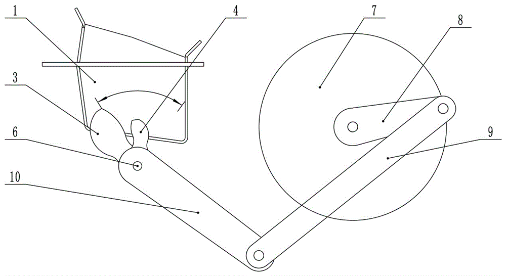
[0035] Such as Figure 2-4 , Figure 5-1 with Figure 5-2 As shown, the slag removal ventilation device includes a rotating shaft 6 and a slag removal tooth piece 3 and a ventilation tooth piece 4 installed on the rotation shaft 6 at intervals. A retaining ring 5 is set so that the slag removal tooth piece 3 and the ventilation tooth piece 5 are inserted into each of the slot-shaped ventilation holes 2 at intervals, and the slag removal tooth piece 3 extends into the interior of the combustion pool 1 so as to break the block The slag, like a knife blade, will forcefully crush the burning residue that is about to slag or has already slagged, and leaks d...

Embodiment 2

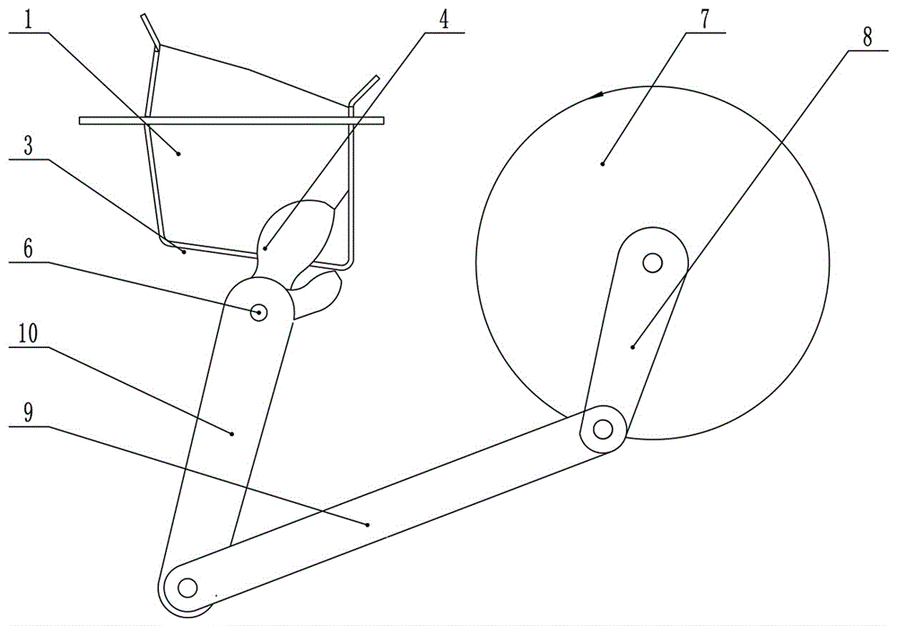
[0045] Such as Figure 7 As shown, an automatic slag removal structure for a biomass pellet fireplace includes a combustion pool 1, a slag removal ventilation device and a power mechanism, wherein the bottom of the combustion pool 1 is provided with multiple rows of slot-shaped ventilation holes 2; the slag removal ventilation The device includes a rotating shaft 6 and a slag removing gear 3 installed on the rotating shaft 6, and a retaining ring 5 is arranged between each of the slag removing gears 3 so that the slag removing gear 3 is respectively inserted into each of the grooves for ventilation. In the hole 2, the free end of the slag removal tooth piece 3 extends into the interior of the combustion pool 1 so as to break the slag; the power mechanism includes a deceleration motor (not shown in the figure) that drives the rotating shaft 6 to rotate. The deceleration motor is connected to the slag removal gear 3 through the rotating shaft 6, and drives the slag removal gear ...


PUM


Abstract

The invention provides an automatic slag removal structure of a biomass particle fireplace. The automatic slag removal structure comprises a combustion pool, a slag removal ventilation device and a power mechanism, wherein a plurality of rows of groove-shaped air vents are formed in the bottom of the combustion pool; the slag removal ventilation device comprises a rotary shaft as well as slag removal tooth sheets and ventilation tooth sheets which are installed on the rotary shaft at intervals, and retaining rings are arranged between the slag removal tooth sheets and the ventilation tooth sheets in a cushioning manner so that the slag removal tooth sheets and the ventilation tooth sheets are inserted in the groove-shaped air vents at intervals and in a staggered manner; a speed reduction motor drives the rotary shaft to carry out reciprocating swing motion through a crank-link mechanism; and included angles are arranged between the slag removal tooth sheets and the ventilation tooth sheets in a manner of corresponding to the groove-shaped air vents, and the swing range of the slag removal tooth sheets and the swing range of the ventilation tooth sheets cover the length of the whole groove-shaped air vents during a swing process. The speed reduction motor drives the rotary shaft to rotate to drive the slag removal tooth sheets to swing, slags are crushed and discharged from the groove-shaped air vents, the groove-shaped air vents are dredged, and the ventilation tooth sheets are mainly used for dredging the groove-shaped air vents which the slag removal tooth sheets cannot arrive at, so that the purposes of slag removal and ventilation in a combustion chamber are achieved.

Description

technical field [0001] The invention relates to a biomass particle combustion slag removal structure, in particular to an automatic slag removal structure for a biomass particle fireplace. Background technique [0002] The existing fireplaces in our country are imported from developed countries such as Western Europe. Western European countries are rich in wood resources, and the use of wood biomass pellet heating fireplaces in those developed countries has become a must for every household. [0003] Therefore, at present, the existing fireplaces in our country can only use high-end, low-ash, non-slagging wood pellets. The pellets burn in a tumbling and boiling manner in the combustion pool, and the residue falls out of the combustion pool by the suction of the fan. For biomass particles with large ash content and easy slagging during combustion, existing fireplaces cannot be used. [0004] In order to solve this problem, China has been exploring reasonable technical soluti...

Claims


Application Information

Patent Timeline
IPC IPC(8): F23J1/06
CPCF23J1/06
Inventor 杨继全蒋海涛
Owner HENAN SHENHOU IND CO LTD
Why Eureka
Try Eureka