Supercharge Your Innovation With Domain-Expert AI Agents!

Water-flow-variable air conditioner tail end and work method thereof

An air-conditioning terminal and working method technology, applied in air-conditioning systems, heating methods, space heating and ventilation, etc., can solve the problems of unbalanced water flow at the terminal, energy waste, insufficient comfort, etc., to ensure energy saving, ensure hydraulic balance, The effect of improving efficiency

Active Publication Date: 2017-05-31
英得艾斯(上海)冷冻空调有限公司
View PDF6 Cites 5 Cited by
  • Summary
  • Abstract
  • Description
  • Claims
  • Application Information

AI Technical Summary

Problems solved by technology

[0005] The object of the present invention is to provide a variable water flow air conditioner terminal and its working method. By setting inlet and outlet water temperature sensors at each parallel air conditioner terminal and setting a waterway regulating solenoid valve before each air conditioner terminal, the front and rear sides of the air conditioner terminal At the same time, the above-mentioned sensors, solenoid valves, fans and fresh air valves at the end of the air conditioner are all monitored by the control center, so as to obtain a more comfortable room temperature and humidity, and at the same time solve the problem of constant water flow at the end and water flow at the end. Issues such as lack of comfort and energy waste caused by unbalanced air volume and fan air volume cannot be automatically adjusted

Method used


Image

  • Water-flow-variable air conditioner tail end and work method thereof
  • Water-flow-variable air conditioner tail end and work method thereof
  • Water-flow-variable air conditioner tail end and work method thereof

Examples


Embodiment 1

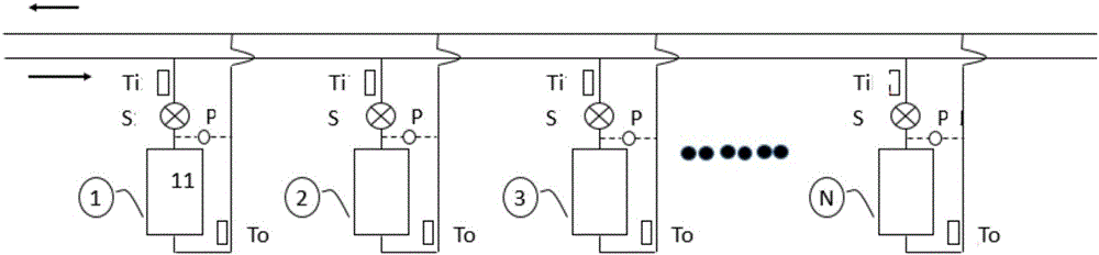
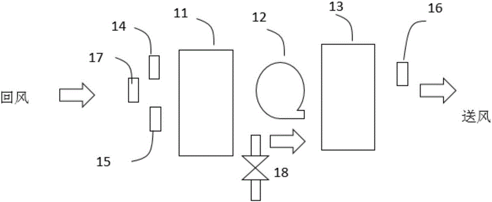
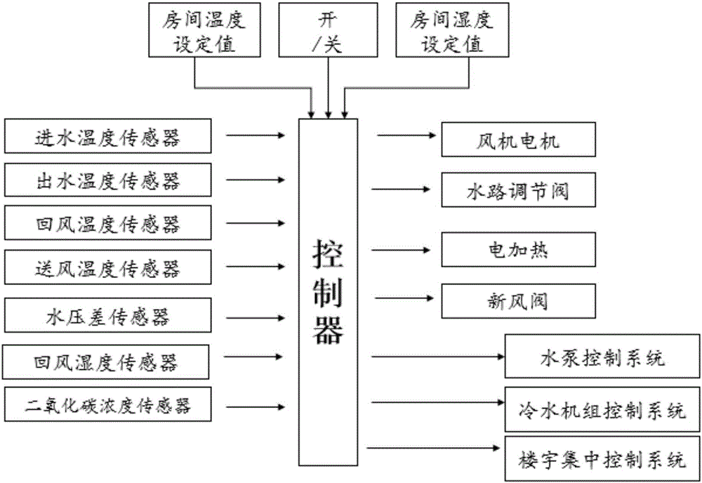
[0035] One air-conditioning terminal: the cooling capacity is 3kW, the rated flow rate is 8.6L / min, the pressure drop under the rated flow rate is 30kPa, the heating capacity is 3.6kW, and the electric heating power is 1kW. Each air-conditioning terminal includes: coil heat exchanger 11, water circuit Electromagnetic regulating valve S, inlet water temperature sensor Ti, outlet water temperature sensor To, differential pressure sensor P, controller, return air temperature sensor 14, outlet air temperature sensor 16, electric heating 13, fan 12, return air humidity sensor 15, carbon dioxide sensor 17. like figure 1As shown, in the direction of water flow, the water circuit electromagnetic regulating valve S is arranged before the coil heat exchanger 11, the inlet water temperature sensor Ti is arranged before the coil heat exchanger 11, and the outlet water temperature sensor To is arranged before the coil heat exchanger After 11, a differential pressure sensor P is connected ...


PUM


Abstract

The invention relates to a water-flow-variable air conditioner tail end. A water way adjusting electromagnetic valve and a water inlet temperature sensor are arranged in front of a coil heat exchanger, and a water outlet temperature sensor is arranged after the coil heat exchanger. The front side and the rear side of the coil heat exchanger pass through a pressure difference sensor. An air return opening of the air conditioner tail end is provided with an air return temperature sensor and an air return humidity sensor. An air outlet of the air conditioner tail end is provided with an air outlet temperature sensor and an electric heating device. The water way adjusting electromagnetic valve, the water inlet temperature sensor, the water outlet temperature sensor, the pressure difference sensor, the air return temperature sensor, the air return humidity sensor, the air outlet temperature sensor and the electric heating device are in signal connection with a control center. The control center receives real-time monitoring data of the water inlet temperature sensor, the water outlet temperature sensor, the pressure difference sensor, the air return temperature sensor, the air return humidity sensor and the air outlet temperature sensor and is used for controlling the opening degree of the water way adjusting electromagnetic valve, running of the electric heating device and the rotating speed of a draught fan.

Description

technical field [0001] The invention relates to a variable water flow air conditioner terminal and a working method thereof, belonging to the technical field of refrigeration equipment. Background technique [0002] The existing air conditioner terminal generally only includes a water solenoid valve, coil heat exchanger, fan, and controller. The indoor return air is blown to the coil heat exchanger after being boosted by the fan, and the water solenoid valve is used to shut off the water flow. supply. There are fan control buttons on the controller to control the speed of the fan, such as high speed, medium speed, and low speed. At the same time, there are switch, cooling and heating setting buttons, as well as temperature setting knobs or buttons. The controller comes with a room Temperature Sensor. When cooling, when the room temperature is higher than the set value, the water solenoid valve is opened, otherwise it is closed; when heating, when the room temperature is lo...

Claims


Application Information

Patent Timeline
IPC IPC(8): F24F1/00F24F11/00F24F13/30
CPCF24F1/0007F24F11/30F24F11/83F24F13/30F24F2110/00F24F2110/10F24F11/84F24F11/85Y02B30/70
Inventor 余红升赵锁民李杰李航郑才娟阎航海
Owner 英得艾斯(上海)冷冻空调有限公司
Features
  • R&D
  • Intellectual Property
  • Life Sciences
  • Materials
  • Tech Scout
  • Unparalleled Data Quality
  • Higher Quality Content
  • 60% Fewer Hallucinations
Learn More