
Micro heat pipe vacuuming and filling device and method

A technology of micro-heat pipe and vacuuming, applied in indirect heat exchangers, lighting and heating equipment, etc., can solve the problems of inaccuracy, high cost of temperature control system, and inability to achieve precise control, etc., and achieve the effect of simple and economical structure

Active Publication Date: 2017-05-31
JIANGSU UNIV
View PDF9 Cites 11 Cited by
  • Summary
  • Abstract
  • Description
  • Claims
  • Application Information

AI Technical Summary

Problems solved by technology

However, this scheme judges the amount of charging fluid by time, and cannot achieve precise control, and the cost of the required temperature control system is high, and the charging time of working fluid is long
The patent with application number 03223886.X and titled "A Micro Heat Pipe Vacuum Liquid Filling Device" constitutes a vacuum pumping and liquid filling device for micro heat pipes through a vacuum loop system, a liquid bypass system and a trace liquid calibration system. Effective device, but the method of accurately controlling the size of the filler mass by clamping the calibration scale on the infusion hose with micro forceps is still not accurate

Method used


Image

  • Micro heat pipe vacuuming and filling device and method
  • Micro heat pipe vacuuming and filling device and method
  • Micro heat pipe vacuuming and filling device and method

Examples


Embodiment Construction

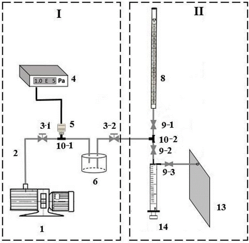
[0030] Such as figure 1 As shown, 1. A micro heat pipe evacuation and filling device is characterized in that it includes a vacuum system I and a filling system II;

[0031] The vacuum system I includes a vacuum pump 1, a metal pipeline 2 and a liquid storage tank 6, one end of the vacuum pump 1 is connected to one end of a section of metal pipeline 2, and the other end of the metal pipeline 2 is placed in the liquid storage tank 6, the port is always above the liquid level in the liquid storage tank 6;

[0032] The filling system II includes a burette 8, a micro-injector 14, a transparent silicone hose 15, and a micro-heat pipe 13;

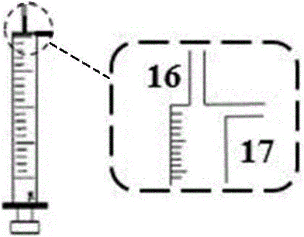
[0033] Such as figure 2 As shown, the microinjector 14 includes a fluid inlet 16 and a fluid outlet 17;

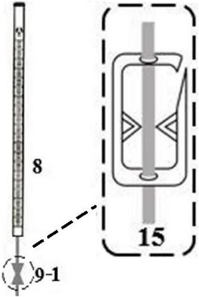
[0034] The burette 8 is connected to one end of the tee B10-2 through a transparent silicone hose 15, and this section of the transparent silicone hose 15 is clamped with a Robert hose clamp A9-1;

[0035] One end of another section of t...


PUM


Abstract

The invention provides a micro heat pipe vacuuming and filling device and method. The micro heat pipe vacuuming and filling device comprises a vacuumizing system and a filling system. The vacuuming system is mainly composed of a vacuum pump, a digital vacuum gauge, a pressure sensor and a liquid storage tank which are sequentially connected. All the parts are connected through a pipeline. The pipeline is controlled by needle valves to be connected and disconnected. The filling system comprises a burette, a trace liquid injector, a transparent silica gel hose and the like. Multiple Robert hose clamps are arranged on different portions of the transparent silica gel hose and capable of achieving the opening / closing functions of similar valves. The device is simple and economical in structure, the vacuumizing and filling processes can be achieved just through operations of the valves in the limited steps, the amount of a filling working medium of a micro heat pipe can be controlled precisely, and the size of a cavity in the micro heat pipe can be measured precisely.

Description

technical field [0001] The invention relates to the technical field of heat pipe packaging, in particular to a vacuumizing and filling device and method for a micro heat pipe, which are used to complete the precise and quantitative filling of working fluid in the micro heat pipe. Background technique [0002] With the increasing integration of electronic circuits and the popularization of smart portable devices, the heat dissipation problem of high heat flux in a small space needs to be solved urgently. Micro heat pipe technology is starting to gain more applications as a viable and efficient cooling solution. In 2014, Sony applied heat pipe technology to mobile phone cooling for the first time. However, the cross-sectional size of such heat pipes is usually as small as a hundred microns, and there are still technical difficulties in how to accurately fill a certain amount of working fluid inside a heat pipe of tens to hundreds of microliters. [0003] In the currently kno...

Claims


Application Information

Patent Timeline
IPC IPC(8): F28D15/02
CPCF28D15/0283
Inventor 屈健李孝军孙芹王谦
Owner JIANGSU UNIV
Learn More