
A non-contact gas leak detection system

A gas leak detection, non-contact technology, applied in the direction of detecting the appearance of fluid at the leak point, using liquid/vacuum for liquid tightness measurement, etc. Safety accidents and other issues to achieve the effect of controlling installation costs

Active Publication Date: 2019-10-11
西安富润嘉业新材料科技有限公司
View PDF7 Cites 0 Cited by
  • Summary
  • Abstract
  • Description
  • Claims
  • Application Information

AI Technical Summary

Problems solved by technology

However, the contact gas detection sensor has the following disadvantages. 1. The gas detection sensor is directly placed on the surface of the storage tank. Most of the gas detection sensors inevitably destroy the protective coating on the surface of the storage tank. The direct impact of this system is The structure of the storage tank around the gas detection sensor is very easy to interact with the corrosion factors of the air; 2. The properties of the gas detection sensor directly in contact with the storage tank structure are quite different from the material properties of the storage tank itself, resulting in the gas detection sensor and the storage tank The surface tissue has a large electrode potential, and the electrochemical corrosion on the surface of the storage tank greatly weakens the safety performance of the storage tank
In order to realize the precise positioning of the gas leakage point, the effective way is to increase the number of gas detectors. Combined with the above two aspects, the traditional contact gas leakage detection system has a greater impact on the damage of the storage tank, which not only reduces The service life of the storage tank is shortened, and the probability of safety accidents is also increased to a certain extent.

Method used


Image

  • A non-contact gas leak detection system
  • A non-contact gas leak detection system
  • A non-contact gas leak detection system

Examples


Embodiment Construction

[0040] Specific embodiments of the present invention will be described in detail below.

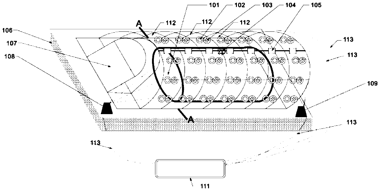
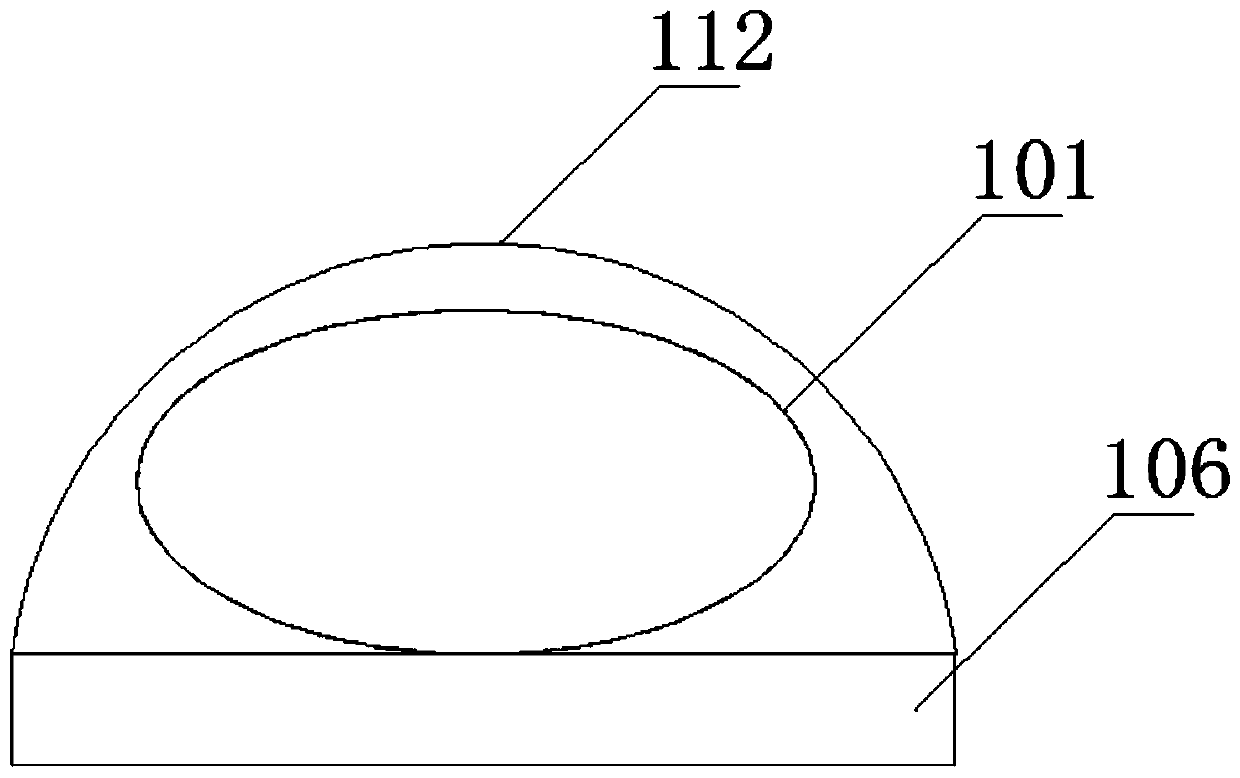
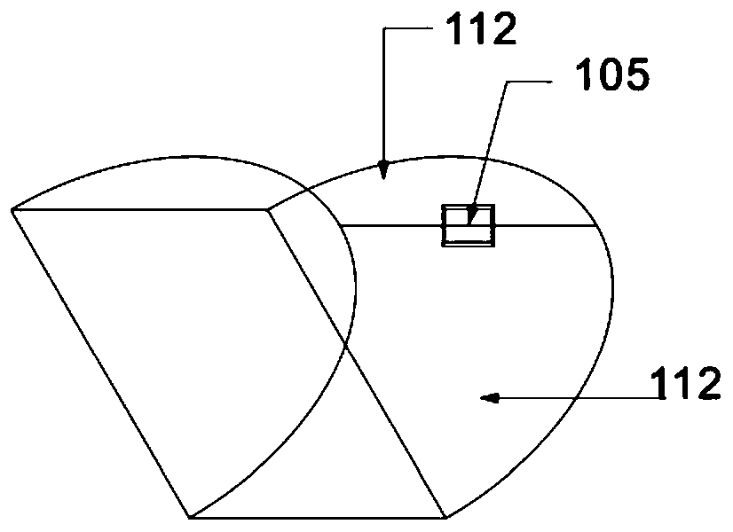
[0041] Such as Figure 1~4 As shown, a non-contact gas leak detection system includes:

[0042] support body 106,

[0043] The gas isolation cover device includes multiple sets of isolation units fixed on the upper surface of the support body 106 arranged parallel to the axis of the horizontal storage tank 101, separated from the horizontal storage tank 101, and used to cover the surface of the horizontal storage tank 101 form a relatively isolated system;

[0044] A plurality of gas detection sensors 102 are arranged at equal intervals on the gas isolation cover device in a manner parallel to the axis of the gas isolation cover device, for real-time monitoring of the concentration of the target gas between the horizontal storage tank 101 and the gas isolation cover device;

[0045] A plurality of gas flow rate sensors 103 are arranged at equal intervals on the gas isolation cover devi...


PUM


Abstract

The invention relates to a non-contact gas leakage detection system, which includes a support body; a gas isolation cover device, which is separated from a horizontal storage tank and used to form a relatively isolated system on the surface of the horizontal storage tank; a plurality of gas detection A sensor is arranged on the gas isolation cover device; a plurality of gas flow rate sensors are arranged on the gas isolation cover device; a temperature sensor is located in the middle of the axis of the gas isolation cover device; a blower is fixed on one side of the gas isolation cover device; The gas detection sensor receiver is located at a corner of the support body and is connected to the gas detection sensor through a cable; the gas flow rate sensor receiver is located at a corner of the support body and is connected to the gas flow rate sensor through a cable; the computer processing system is connected to the gas detection sensor The receiver, gas flow rate sensor receiver, and temperature sensor are connected through signal lines and are used to receive and process the collected feedback data and real-time data.

Description

technical field [0001] The invention relates to the field of industrial production, in particular to a non-contact gas leakage detection system. Background technique [0002] At present, natural gas in production and living places such as gas stations is usually stored in horizontal storage tanks. Generally, the pressure of natural gas in horizontal storage tanks is more than ten atmospheres, and the natural gas stored in them is also corrosive to a certain extent. , such a horizontal storage tank is in a complex physical and chemical environment, and all structural performance indicators must meet higher requirements, so it is particularly important for the structural detection and protection of horizontal storage tanks. [0003] The gas stored in the horizontal storage tank is generally flammable and toxic. If the operation is improper or the management facilities and equipment are aging or malfunctioning, the high-pressure flammable gas inside may easily leak and cause a ...

Claims


Application Information

Patent Timeline
Patent Type & Authority Patents(China)
IPC IPC(8): G01M3/04
Inventor 胡军薛文博王祯王甜甜马晓迅
Owner 西安富润嘉业新材料科技有限公司
Learn More