A Subway Tunnel Leakage Monitoring and Early Warning Method
A tunnel and subway technology, applied in the field of subway tunnel leakage monitoring and early warning system, to avoid interference
- Summary
- Abstract
- Description
- Claims
- Application Information
AI Technical Summary
Problems solved by technology
Method used
Image
Examples
Embodiment 1
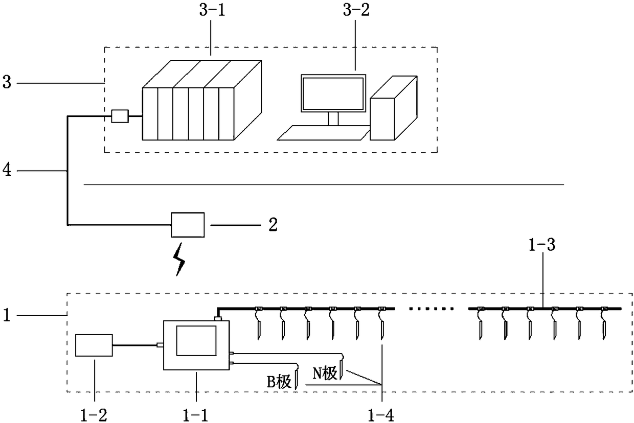
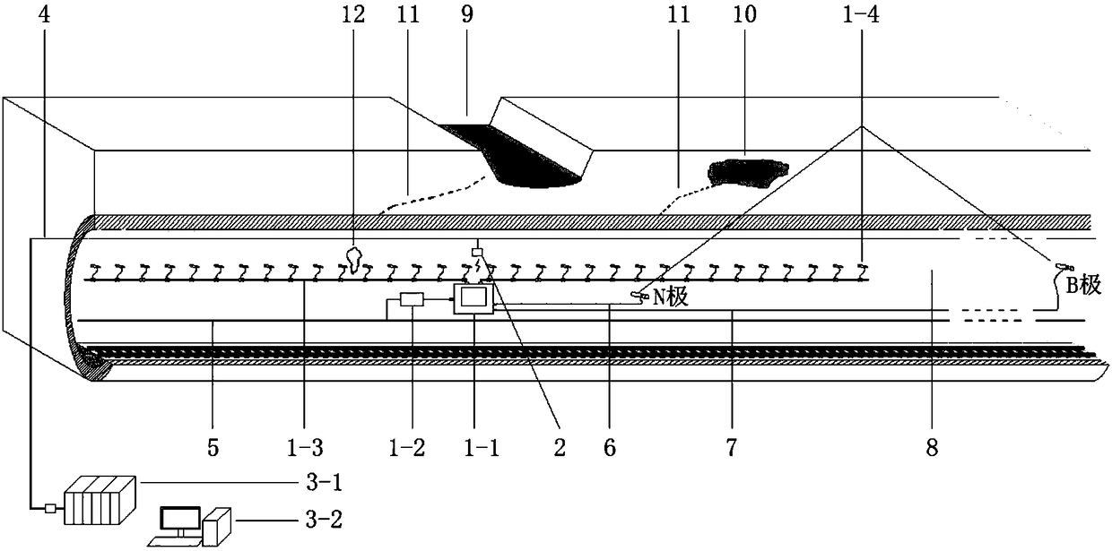
[0031] like figure 1 As shown, the subway tunnel leakage monitoring and early warning system of this embodiment includes a parallel electrical method acquisition subsystem 1 , a wifi gateway 2 and a data monitoring subsystem 3 . The parallel electrical method acquisition subsystem 1 includes a parallel electrical method instrument host 1-1, a power conversion device 1-2, an electrical method large line 1-3, and electrodes 1-4, which are used to realize the on-site electrical measurement of the tunnel to obtain the electrical method. legal data.
[0032] The wifi gateway 2 is connected to the Ethernet 4 inside the tunnel, and is installed near the host 1-1 of the parallel electrical instrument for network link and instant communication between the data monitoring subsystem and the parallel electrical acquisition subsystem. Of course, the wifi gateway 2 can also adopt wired transmission, or a satellite communication system to realize network link and instant messaging.
[0033] ...
Embodiment 2
[0037] Determine the distribution position of electrodes 1-4 according to the observation method in the layout plan, the distance between electrodes 1-4, the number of electrodes, and the length of the measuring line. The following principles should be followed: In general, the distance between electrodes 1-4 is 1-5m. If the detection accuracy is high, it is better to take 1-2m, and the key areas should be properly encrypted, and the length of the measuring line can be traced continuously In general, the infinity B pole is buried at the far end of 3 to 5 times the length of the survey line, and the common N pole is buried in the normal field far away from the percolation zone and the electric field is stable. Any location; the installation of electrodes 1-4 should avoid the power cables and other facilities in the tunnel 8; it should penetrate the tunnel wall and have no contact with the metal in the wall, and behind the tunnel wall, the electrodes 1-4 should be protected after...
Embodiment 3
[0059] like Figure 4a and Figure 4b As shown, this embodiment mainly uses the parallel electrical acquisition subsystem 1 to conduct seepage detection experiments on the built physical model system. in Figure 4a It is a schematic diagram of the seepage detection model system and measurement layout. The potential difference between the 1#-20# electrode 22 and the N pole is extracted synchronously, and the variation curve of the natural electric field with the electrode at multiple times is obtained, that is, the natural potential isochrone of the seepage process changes with the electrode. changing fluctuation curve, Figure 4b .
PUM
 Abstract
Description
Claims
Application Information
 - R&D
- Intellectual Property
- Life Sciences
- Materials
- Tech Scout
- Unparalleled Data Quality
- Higher Quality Content
- 60% Fewer Hallucinations
Browse by: Latest US Patents, China's latest patents, Technical Efficacy Thesaurus, Application Domain, Technology Topic, Popular Technical Reports.
© 2025 PatSnap. All rights reserved.Legal|Privacy policy|Modern Slavery Act Transparency Statement|Sitemap|About US| Contact US: help@patsnap.com


