
Wind tunnel test stand with unilateral aerodynamic force

A wind tunnel experiment and aerodynamic technology, which is applied in the aerospace field, can solve the problems of flutter and small stiffness of thin plates, and achieve the effect of simple and reliable structural design, high universality of parts and low manufacturing cost

Pending Publication Date: 2017-05-31
NANJING UNIV OF AERONAUTICS & ASTRONAUTICS
View PDF8 Cites 1 Cited by
  • Summary
  • Abstract
  • Description
  • Claims
  • Application Information

AI Technical Summary

Problems solved by technology

[0006] The purpose of the present invention is to provide a wind tunnel test frame for unilateral aerodynamic force, which is used to solve the shortcomings of testing bilateral aerodynamic force, thin plates are prone to flutter, and the stiffness is small.

Method used


Image

  • Wind tunnel test stand with unilateral aerodynamic force
  • Wind tunnel test stand with unilateral aerodynamic force
  • Wind tunnel test stand with unilateral aerodynamic force

Examples


Embodiment Construction

[0022] Below in conjunction with accompanying drawing and specific embodiment the present invention is described in detail:

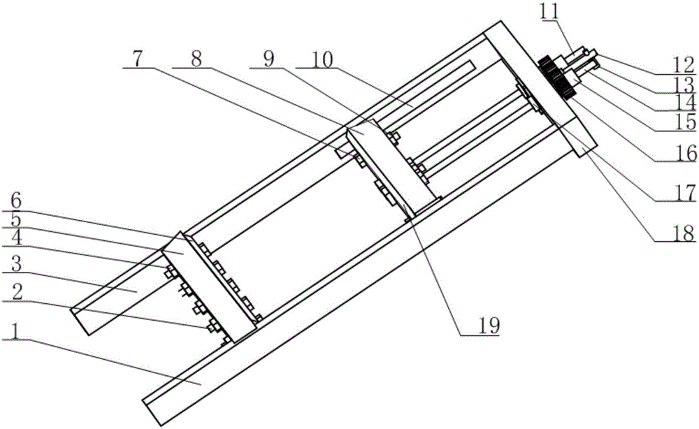
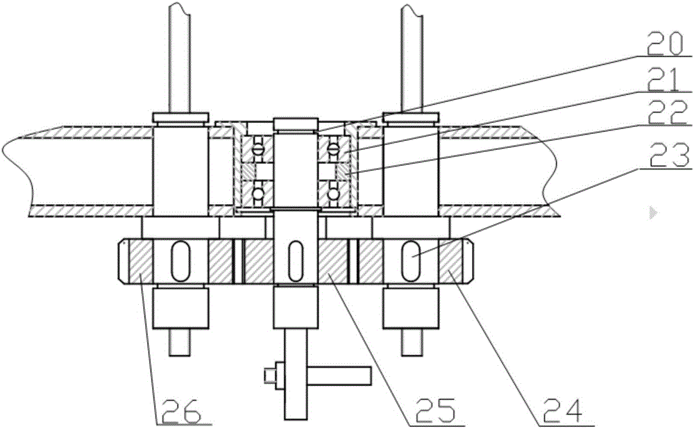
[0023] The unilateral aerodynamic wind tunnel test frame of the present invention has an overall structure such as figure 1 and 5 As shown, including right support plate 1, first bolt 2, left support plate 3, first nut 4, front deflector 5, front deflector splint 6, second bolt 7, rear deflector 8, second nut 9. Linear guide rail 10, first lead screw 11, handle guide rod 12, handle 13, second lead screw 14, cylindrical nut 15, gear 16, sleeve 17, rear support plate 18, rear deflector splint 19, spring coil 20, bearing 21, bobbin 22, key 23, right gear 24, intermediate gear 25, left gear 26, dial 27 and thin plate 28. The right support plate 1 and the left support plate 3 are placed in parallel, and the right support plate 1 and the left support plate 3 are welded together by the rear support plate 18 .

[0024] The front deflector 5 and the front def...


PUM


Abstract

The invention provides a wind tunnel test stand with a unilateral aerodynamic force. A handle is rocked to provide power; the handle is rocked, a middle gear drives a left gear and the right identical gear to rotate in the same direction, and rotation of the left gear and the right gear drives a first screw rod and a second screw rod to move forwardly; a rear flow guide clamping plate moves along a linear guide rail under pulling force effects of the first screw rod and the second screw rod; drawing of a thin plate is driven through the pulling force of the first screw rod and the second screw rod and the traction force of the linear guide rail; the rotation angles of the first screw rod and the second screw rod can be measured by a rotation disc; and the drawing distance of the thin plate can be obtained according to pitches of the first screw rod and the second screw rod. The wind tunnel test stand with the unilateral aerodynamic force has the advantages that reverse engagement of the gears controls movement of the first screw rod and the second screw rod to achieve high precision and high reliability, movement of the first screw rod and the second screw rod can be controlled only by rotating the handle, the operation is extremely simple, the overall structure is simple, the weight is light and the like.

Description

[0001] Technical field: [0002] The invention relates to a unilateral aerodynamic wind tunnel test frame, which belongs to the field of aerospace. [0003] Background technique: [0004] At present, aerodynamic experiments are divided into two categories: physical experiments and model experiments. When conducting model experiments, the similarity between the model flow field and the real flow field should be ensured, that is, in addition to ensuring the geometric similarity between the model and the real object, the similarity criteria related to the two flow fields, such as Reynolds number, Mach number, general The Randt numbers and so on are correspondingly equal. Therefore, there must be certain requirements for the experimental frame with unilateral aerodynamic force. The airflow cannot flow on the two surfaces of the aircraft skin, but can only be limited to one surface. The low-speed flow simulates the supersonic condition, and the strength of the thin plate must be i...

Claims


Application Information

Patent Timeline
Patent Type & Authority Applications(China)
IPC IPC(8): G01M9/04
CPCG01M9/04
Inventor 陈娜娜于明礼王立峰
Owner NANJING UNIV OF AERONAUTICS & ASTRONAUTICS
Learn More