Double rotor test machine for cylindrical roller bearings

A technology of cylindrical roller bearings and double rotors, which is applied in the direction of mechanical bearing testing, etc., and can solve the problems of low limit speed, no large size, high speed and large load cylindrical roller bearing test double rotor testing machine, harsh working environment, etc. , to achieve the effect of increasing the maximum speed, high positioning accuracy, and good loading smoothness

Active Publication Date: 2017-05-31
HENAN UNIV OF SCI & TECH
View PDF4 Cites 8 Cited by
  • Summary
  • Abstract
  • Description
  • Claims
  • Application Information

AI Technical Summary

Problems solved by technology

The R&D, design, manufacture and test technology of high-temperature and high-speed precision inter-axial bearings are mainly monopolized by a few foreign countries. The research and development of this type of testing machine in my country began in the 1970s and 1980s. Due to the limitations of design and manufacturing at that time, The inner and outer diameters of test bearings are also limited to medium and small sizes, and the limit speed is also low, which cannot meet the current test requirements for inter-shaft bearings with an inner diameter greater than 110mm and an outer diameter greater than 140mm, high temperature and high speed
[0003]Especially for high-temperature, high-speed precision inter-axial cylindrical roller bearings whose inner and outer rings rotate at the same time during operation, the test standards are more stringent because of the harsh working environment , there is no dual-rotor testing machine that can complete the test of large-size, high-speed, and heavy-load cylindrical roller bearings in the existing test equipment

Method used


Image

  • Double rotor test machine for cylindrical roller bearings
  • Double rotor test machine for cylindrical roller bearings
  • Double rotor test machine for cylindrical roller bearings

Examples


Embodiment Construction

[0042] Embodiments of the present invention will be specifically described below with reference to the accompanying drawings.

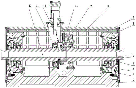
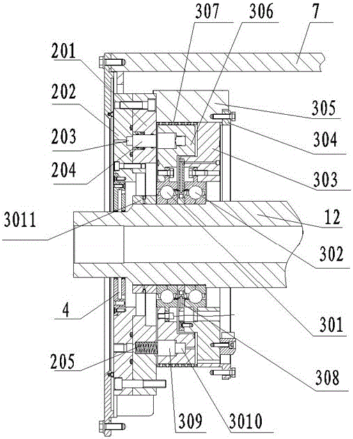
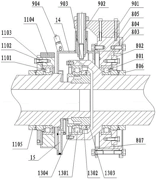
[0043] A cylindrical roller bearing double-rotor testing machine, comprising a body base 1, a rotor shaft arranged on the body base 1, a radial loading device 10 arranged above the rotor shaft and fixedly connected to the body base 1, and a monitoring device 9, the rotor A first accompanying test device 11 , a test bearing tooling 13 and a second accompanying test device 8 are sequentially arranged on the shaft, and a supporting device 3 is respectively provided at both ends of the rotor shaft.

[0044] The rotor shaft is composed of an inner ring rotor shaft 12 and an outer ring rotor shaft 5, and both the inner ring rotor shaft 12 and the outer ring rotor shaft 5 are hollow shafts. The test bearing tooling 13 is composed of a test bearing 1301, a fourth stepped sleeve 1302, an under-ring lubricating sleeve 1303 and a test bearing pressure ring 1304,...


PUM


Abstract

Provided is a double rotor test machine for cylindrical roller bearings. The double rotor test machine comprises a body frame, a rotor shaft, a radial loading device, and a monitoring device, wherein the rotor shaft is arranged on the body frame, and the radial loading device is arranged above the rotor shaft and is fixedly connected with the body frame; the rotor shaft is in turn provided with a first assistant test device, a test bearing fixture and a second assistant test device; the two ends of the rotor shaft are also respectively provided with a support device; the rotor shaft is composed of an inner rotor shaft and an outer rotor shaft; a lower ring lubricating sleeve of the test bearing fixture is sleeved at the test end of the inner rotor shaft; a test bearing is sheathed on the lower ring lubrication sleeve; the outer ring of the test bearing is pressed in the inner hole of outer rotor shaft test end; the support device comprises an axially loaded bearing and a support bearing arranged in parallel, the supporting bearing is positioned inside of the axially loaded bearing, and an axial loading device is also arranged outside of the axial loading bearing. The test process of the double rotor test machine for the cylindrical roller bearings is scientific and can effectively test various parameters of large bearings at high speed.

Description

technical field [0001] The invention relates to a bearing testing machine, in particular to a cylindrical roller bearing double-rotor testing machine. Background technique [0002] Bearing is an important and key basic component in equipment manufacturing, which directly determines the performance, reliability and life of the equipment; due to the harsh working environment and complex load conditions of the bearing, it must be long enough or even the entire life cycle of the equipment to avoid Maintenance, etc. During the design, development and manufacturing process, the bearings must be verified on the testing machine for corresponding simulated working conditions to provide reliable test data for research, design, manufacture and use, and provide a basis for the design, manufacture and use of bearings . The R&D, design, manufacture and test technology of high-temperature and high-speed precision inter-axial bearings are mainly monopolized by a few foreign countries. The ...

Claims


Application Information

Patent Timeline
Patent Type & Authority Applications(China)
IPC IPC(8): G01M13/04
CPCG01M13/04
Inventor 司东宏李济顺于伟涛薛玉君马伟
Owner HENAN UNIV OF SCI & TECH
Why Eureka
Try Eureka