Automatic magnetic field compensation device and method

A magnetic field, automatic technology, applied in the direction of magnetic field offset compensation, measurement device, measurement of magnetic variables, etc., can solve the problem of small magnetic field compensation range, and achieve the effect of large magnetic field compensation range, convenient operation and simple structure

Active Publication Date: 2017-05-31
WUHAN INST OF PHYSICS & MATHEMATICS CHINESE ACADEMY OF SCI
View PDF23 Cites 18 Cited by
  • Summary
  • Abstract
  • Description
  • Claims
  • Application Information

AI Technical Summary

Problems solved by technology

It solves the problem of small magnetic field compensation range an

Method used


Image

  • Automatic magnetic field compensation device and method
  • Automatic magnetic field compensation device and method
  • Automatic magnetic field compensation device and method

Examples


Embodiment 1

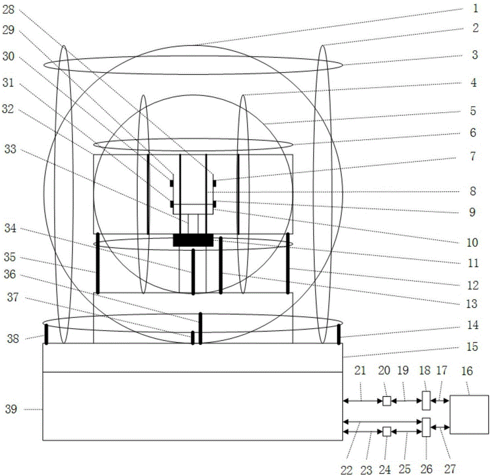
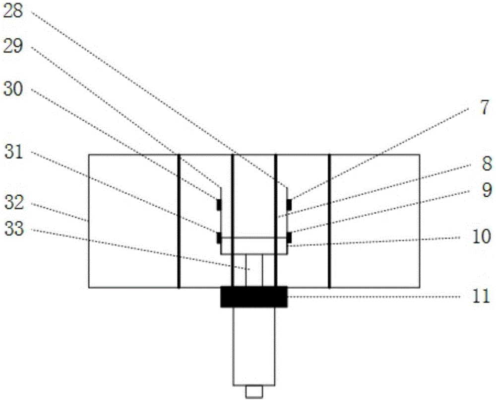
[0036] A device for automatic magnetic field compensation, comprising a rotary table 15, and also includes a three-dimensional Helmholtz coil and a three-dimensional first-order gradient coil arranged on the rotary table 15, and a cylindrical plexiglass tube 32 is arranged laterally on the rotary table 15, The plexiglass tube 32 is wound with a Z2 gradient coil 8, the plexiglass tube 32 is fixed with a support platform 10 by a support rod, and the support platform 10 is provided with the first magnetoresistive chip 7 and the first magnetoresistive chip 7 positioned at the four corners of the rectangular surface Two magnetoresistance chips 9, the third magnetoresistance chip 30 and the fourth magnetoresistance chip 31, the angle between the rectangular surface and the horizontal plane is 45 degrees, the three-dimensional Helmholtz coil includes the X-axis Helmholtz coil 5, the Y-axis 1 The Holtz coil 6 and the Z-axis Helmholtz coil 4, the three-dimensional first-order gradient c...

Embodiment 2

[0044] A device for automatic magnetic field compensation, including a fixed unit, a support unit, a three-dimensional Helmholtz coil, a three-dimensional first-order gradient coil, a second-order gradient coil unit, an acquisition unit, a feedback unit, and a rotation unit.

[0045] The fixed unit comprises a rectangular placement block 11, a first fixed rod 12, a second fixed rod 13, a third fixed rod 14, a fourth fixed rod 34, a fifth fixed rod 35, a sixth fixed rod 36, a seventh fixed rod 37, The eighth fixed rod 38, the rectangular placing block 11 is a rectangle as a whole, fixed on the support bar 33, the top surface of the rectangular placing block 11 is provided with a strip-shaped placing groove, the cross-section of the placing groove is an inverted triangle, and the organic glass tube 32 Placed on the placement groove on the rectangular placement block 11, the first fixed rod 12, the second fixed rod 13, the fourth fixed rod 34 and the fifth fixed rod 35 are distrib...

Embodiment 3

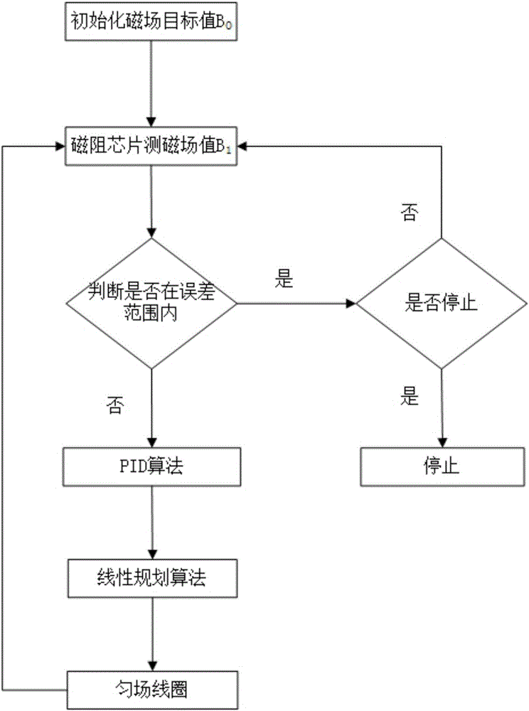
[0094] A method for automatic magnetic field compensation utilizing embodiment 1 or embodiment 2, comprising the following steps:

[0095] step 1,

[0096] Load the given voltages -2V, -1.5V, -1V, -0.5V, 0V, 0.5V, 1V, 1.5V, 2V to the X-axis Helmholtz coil 5 sequentially, and use the first magnetoresistive chip 7 to test each The magnitude of the magnetic field value corresponding to the given voltage value, linearly fitting the ratio relationship between the given voltage and the magnetic field of the X-axis Helmholtz coil 5;

[0097] Load the given voltages -2V, -1.5V, -1V, -0.5V, 0V, 0.5V, 1V, 1.5V, 2V to the Y-axis Helmholtz coil 6 sequentially, and use the first magnetoresistive chip 7 to test each The magnitude of the magnetic field value corresponding to the given voltage value, linearly fitting the ratio relationship between the given voltage and the magnetic field of the Y-axis Helmholtz coil 6;

[0098] Load the given voltages -2V, -1.5V, -1V, -0.5V, 0V, 0.5V, 1V, 1...


PUM


Abstract

The invention discloses an automatic magnetic field compensation device. The automatic magnetic field compensation device comprises a first magnetic reluctance chip, a second magnetic reluctance chip, a third magnetic reluctance chip and a fourth magnetic reluctance chip which are used for measuring the magnetic field value in an outside environment and further comprises a fixing unit, a support unit, a collection unit, a feedback unit and a rotation unit as well as three-dimensional Helmholtz coils, three-dimensional one-order gradient coil and a two-order gradient coil unit which are used for shimming. The invention further discloses an automatic magnetic field compensation method. The magnetic field compensation range is large, the device is simple in structure and convenient to operate, and the device and method are applicable to physical field research based on low-magnetic-field environment signal detection and atom magnetometer and have great significance.

Description

technical field [0001] The invention belongs to the field of magnetic field shimming, and more specifically relates to a device for automatic magnetic field compensation, and also relates to a method for automatic magnetic field compensation, which is suitable for relevant scientific research in low magnetic field environments. Background technique [0002] The magnetic field exists objectively. For example, the magnetic field on the surface of the earth is about 0.5 Gauss. Its size and direction will change depending on the geographical location and environment. [0003] Now a lot of scientific research needs to be carried out in a low magnetic field or near zero magnetic field environment, such as the SERF (spin-exchange-relaxation-free) atomic magnetometer, when its probe is in a 10nT environment, it can work effectively. Therefore, it needs to use multiple Layer permalloy and other materials to shield the magnetic field in the external environment. [0004] The shieldin...

Claims


Application Information

Patent Timeline
IPC IPC(8): G01R33/00
CPCG01R33/0017
Inventor 周欣肖康达孙献平赵修超孔霞叶朝辉
Owner WUHAN INST OF PHYSICS & MATHEMATICS CHINESE ACADEMY OF SCI
Why Eureka
Try Eureka