Optical module capable of self-sink type unlocking and shell structure of optical module

An optical module and self-sinking technology, applied in the field of optical modules, can solve the problems of high cost of structural parts, reduced service life, complicated assembly, etc., and achieve the effect of simple installation and easy operation

Active Publication Date: 2017-05-31
WUHAN TELECOMM DEVICES
View PDF1 Cites 11 Cited by
  • Summary
  • Abstract
  • Description
  • Claims
  • Application Information

AI Technical Summary

Problems solved by technology

[0010] That is to say, the slider of the existing optical module must be connected to the bottom case by means of two pressing blocks, and the slider must be returned to its original position by means of an additional biasing member, so that the existing optical module The number of structural parts of the unlocking device is large, the assembly is complicated, and the cost of the structural parts is relatively high
[0011] The application number is: 201210175558.4 Chinese invention patent application "An Unlocking Mechanism for SFP Optical Module". The unlocking slider is set above the slope, such as figure 1 and 2 As shown, when unlocking, the unlocking slider is in contact with the slope, and the lock head is pushed into the inside of the optical module through the slope to realize unlocking, but it has the following disadvantages: when unlocking Multiple operating steps are still required, and the push-pull method will cause a large interaction force between the motor parts due to the instantaneous force generation and instantaneous force restraint process, reducing the service life during the period
like image 3 As shown, although compared with the patent 201210175558.4, there has been a corresponding simplification in the operation engineering, but because it is still not separated from the use of the elastic device, the locking stability will decrease with the increase of the use time

Method used


Image

  • Optical module capable of self-sink type unlocking and shell structure of optical module
  • Optical module capable of self-sink type unlocking and shell structure of optical module
  • Optical module capable of self-sink type unlocking and shell structure of optical module

Examples


Embodiment 1

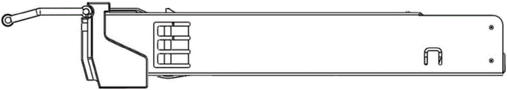
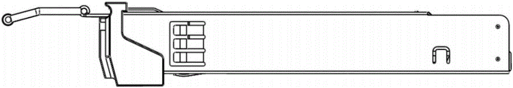
[0064] Embodiment 1 of the present invention provides a self-sinking unlocked optical module housing structure, such as Figure 4-7 As shown, it includes: a base 1, an upper cover 3, a rotating projection 5, a pole 8 and a pull ring 9, and it is characterized in that the rotating projection 5 includes a first connecting piece 5-1, a projection 5-2, The second connecting piece 5-3 and the main body 5-4, wherein the first connecting piece 5-1 and the second connecting piece 5-3 are respectively horizontally located at both ends of the main body 5-4, and the protrusion 5 -2 is located on the main body 5-4; the pull ring 9 includes a fixed shaft 9-1, a rotating shaft 9-2 and a side bar 9-4, wherein the rotating shaft 9-2 is located in the middle of the fixed shaft 9-1 , and protrude from the fixed shaft 9-1, and are used to generate a torque that drives the pole 8 through the rotating shaft 9-2 when the pull ring 9 rotates around the fixed shaft 9-1:

[0065] The second connectin...

Embodiment 2

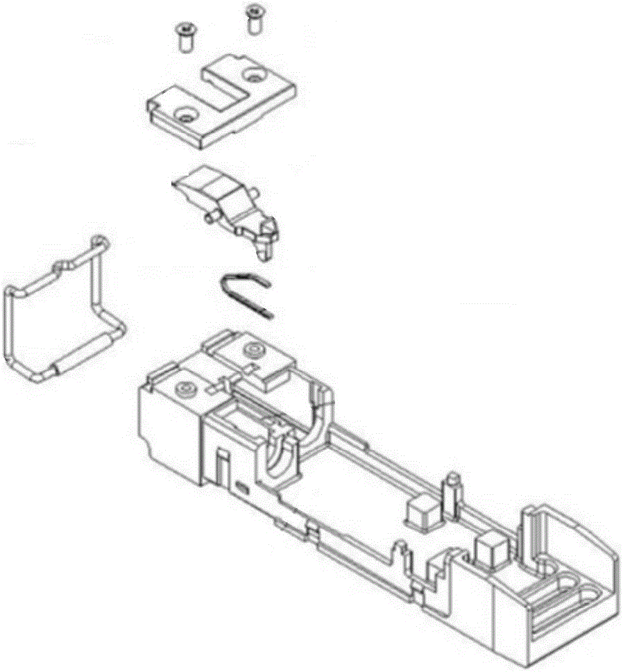
[0080] The embodiment of the present invention also provides a self-sinking unlocking optical module structure, such as Figure 13-15 shown (see attached Figure 5-7 ), including: base 1, PCB board 2, upper cover 3, rotating bump 5, cover plate 6, ROSA7, pole 8, pull ring 9, TOSA10 and all-inclusive shrapnel 11, the PCB board 2, ROSA7 and TOSA10 Located on the base 1 and fixed by the upper cover 3, the all-encompassing elastic piece 11 is fixed on the outer ring of the base 1 and the upper cover 3, and the rotating protrusion 5 includes a first connecting piece 5-1, The bump 5-2, the second connecting piece 5-3 and the main body 5-4, wherein the first connecting piece 5-1 and the second connecting piece 5-3 are respectively horizontally located at both ends of the main body 5-4 , the bump 5-2 is located on the main body 5-4; the pull ring 9 includes a fixed shaft 9-1, a rotating shaft 9-2 and a side bar 9-4, wherein the rotating shaft 9-2 is located In the middle of the fixe...


PUM


Abstract

The present invention belongs to the optical module technical field and provides an optical module capable of self-sink type unlocking and a shell structure of the optical module. The shell structure comprises a base, an upper cover, a rotary projecting block, a supporting rod and a pull ring; the second connecting component of the rotary projecting block is arranged on the base; the first connecting component of the rotary projecting block is connected with the right connecting component of the supporting rod; the left hole of the supporting rod is connected with the rotation shaft of the pull ring; when the pull ring is closed so as to perform locking operation, the rotation shaft drives the supporting rod to generate a traction force to the first connecting component of the rotary projecting block, and the rotary projecting block rotates around the fixed connecting component towards the upper cover under the effect of the traction force; and a slot structure through which the projecting block can pass is formed in the upper cover. According to the optical module capable of self-sink type unlocking and the shell structure of the optical module of the invention, a self-sink type unlocking assembly is realized in the optical module, no springs exist in the self-sink type unlocking assembly, and therefore, easiness in installation can be realized; and when the pull ring is pulled back, the rotary projecting block is reset; in an unlocking process, the rotary projecting block sinks, and therefore, operation is simple.

Description

[0001] 【Technical field】 [0002] The invention relates to the technical field of optical modules, in particular to a self-sinking unlocked optical module and its housing structure. [0003] 【Background technique】 [0004] The steady development of the global telecommunications industry and the steady growth of broadband users have laid a solid foundation for the development of the optical communication industry. By the end of 2015, there were about 740 million fixed broadband users worldwide, a net increase of about 30 million over the previous year. With the continuous improvement of global bandwidth requirements and the expansion of optical communication industry applications such as data centers and security monitoring, optical fiber broadband access has become the mainstream communication mode. Driven by the popularization of smart phones and other terminals, video applications and cloud computing, telecom operators will continue to invest in the construction and upgrade ...

Claims


Application Information

Patent Timeline
Patent Type & Authority Applications(China)
IPC IPC(8): G02B6/42
CPCG02B6/4201G02B6/4256G02B6/4261E05C3/02H05K5/0221H05K5/03
Inventor 梅凯江毅全本庆
Owner WUHAN TELECOMM DEVICES
Why Eureka
Try Eureka