Display panel compatible with multiple types of frame sizes and light-on test method of display panel

A display panel and size technology, applied in nonlinear optics, instruments, optics, etc., can solve the problems of increasing the panel process time and increasing the cost of the mask, and achieve the effect of reducing the cost of the mask, increasing the production capacity, and reducing the process time.

Inactive Publication Date: 2017-05-31
SHENZHEN CHINA STAR OPTOELECTRONICS TECH CO LTD
View PDF3 Cites 11 Cited by
  • Summary
  • Abstract
  • Description
  • Claims
  • Application Information

AI Technical Summary

Problems solved by technology

[0003] Due to the different positions of the shorting bar and the binding lead end of the display panel with different frame sizes, the traditional method is to design two sets of different photomasks to produce two panels with different f

Method used


Image

  • Display panel compatible with multiple types of frame sizes and light-on test method of display panel
  • Display panel compatible with multiple types of frame sizes and light-on test method of display panel
  • Display panel compatible with multiple types of frame sizes and light-on test method of display panel

Examples


no. 1 example

[0033] This embodiment is described by taking the wiring on the side of the source driving circuit of a display panel compatible with two frame sizes as an example.

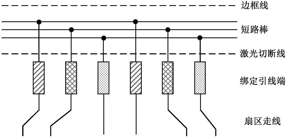
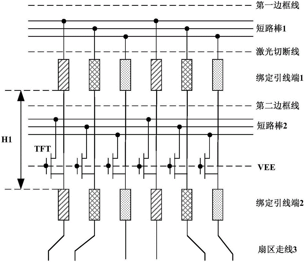
[0034] figure 2 It is a structural schematic diagram of a display panel compatible with multiple frame sizes according to the first embodiment of the present invention. As shown in the figure, the first dotted line from top to bottom in the figure is the frame line corresponding to the first frame size. Panels are wide bezels. The third dotted line is the border line corresponding to the second border size, and the display panel has a narrow border at this time.

[0035] The display panel in this embodiment is used to be compatible with the first frame size and the second frame size, assuming that the first frame size is larger than the second frame size. Such as figure 2As shown, each binding lead end 1 corresponding to the first frame size is connected to the terminal at the corresponding bit sequence of e...

no. 2 example

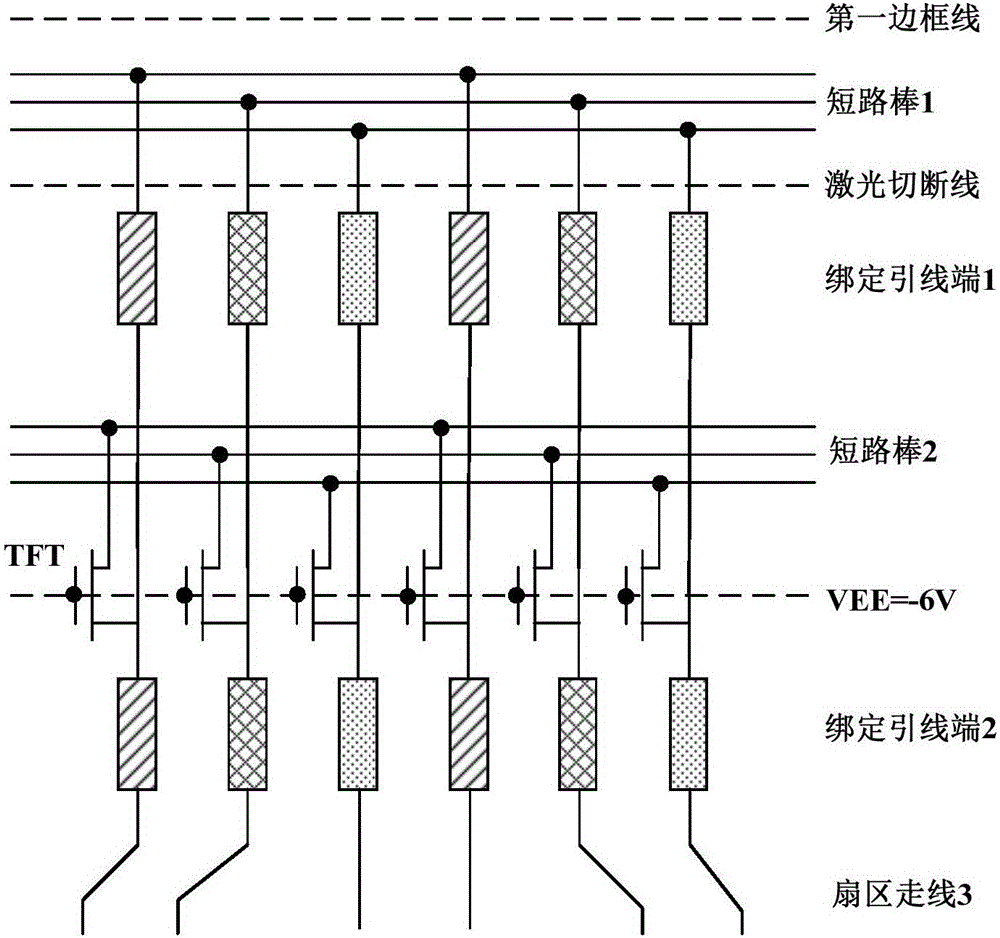
[0044] Figure 5 It is a schematic structural diagram of a display panel compatible with various frame sizes according to the second embodiment of the present invention. In this embodiment, the difference from the first embodiment lies in the location of the switch element.

[0045] As shown in the figure, the thin film transistor is still used as the switching element for illustration, and the thin film transistor is arranged in the area of ​​the sector wiring 3 of the display panel to control the switching of the shorting bar 2 and the binding lead terminal 2 .

[0046] In this embodiment, the distance between the binding lead end 1 and the binding lead end 2 is H2, compared to the distance H1 between the binding lead end 1 and the binding lead end 2 in the first embodiment (such as figure 2 shown), H2


PUM


Abstract

The invention discloses a display panel compatible with multiple types of frame sizes and a light-on test method of the display panel. According to the display panel, a group of binding wire lead ends and multiple pieces of short circuit bars are respectively arranged in a display panel area demarcated by each type of frame size, and the size parameters corresponding to the binding wire lead ends of different frame sizes are the same, wherein the short circuit bars are arranged near the frame lines demarcated by different frame sizes; the binding wire lead ends of a location sequence corresponding to each group of binding wire lead ends after being serially connected in sequence are connected with a fan section routing of the display panel; the binding wire lead end corresponding to the largest frame size is directly connected with the corresponding short circuit bar, and the binding wire lead ends corresponding to the rest frame sizes are connected with the corresponding short circuit bars through a switch component. The display panel can be produced by adopting one type of photomask, the cost of the photomask can be lowered, meanwhile the processing time can be shortened, and the production capacity can be increased.

Description

technical field [0001] The invention belongs to the technical field of liquid crystal display, and in particular relates to a display panel compatible with various frame sizes and a lighting test method for the display panel. Background technique [0002] In recent years, with the rapid development of the display industry, display products have become more and more diversified. Different customers often have different requirements for panel specifications, such as resolution, contrast, penetration rate, frame size and so on. Panel manufacturers are usually faced with the requirement that the two bezels have the same other panel parameters. For masks with different frame sizes but the same panel parameters, except for the Shorting Bar and Bounding Lead, other wiring is the same. [0003] Due to the different positions of the shorting bar and the binding lead end of the display panel with different frame sizes, the traditional method is to design two sets of different photom...

Claims


Application Information

Patent Timeline
IPC IPC(8): G02F1/1345G02F1/13
Inventor 应见见杜鹏
Owner SHENZHEN CHINA STAR OPTOELECTRONICS TECH CO LTD
Why Eureka
Try Eureka