Quick calibration method for robot vision system

A robot vision and calibration method technology, applied in the field of machine vision system calibration, can solve the problems of reduced efficiency, low distortion matrix efficiency, and increased influence of CCD camera detection accuracy, and achieves the effect of speeding up the calculation speed

Active Publication Date: 2017-05-31
XIAMEN UNIV OF TECH
View PDF4 Cites 27 Cited by
  • Summary
  • Abstract
  • Description
  • Claims
  • Application Information

AI Technical Summary

Problems solved by technology

Now more methods are to use the early checkerboard calibration program to directly calibrate the camera, and the calibration of the robot and the camera is mostly assisted by the calibration tool, and now the camera is installed at the end of the robot arm, and the calibration tool is used for hand-eye calibration. Calibration also has a faster speed, but due to the needs of some work, it is not suitable to fix the CCD camera at the end of the robot. The robot vision system with a fixed CCD has the following defects:
[0003] (1) The acquisition speed of camera internal parameters and distortion matrix is ​​slow. For the calibration of CCD cameras, most of them use the checkerboard calibration program to calibrate. Different cameras, different installation distances and lens focal lengths will produce different distortions, so often after the equipment is installed Afterwards, the acquisition of the camera distortion matrix will be carried out, which is used for correction after image acquisition in future work. The speed of image correction using the camera internal parameters and distortion matrix is ​​often very fast, but the efficiency of obtaining the distortion matrix is ​​very low. It will waste a lot of time for installation and debugging personnel;
[0004] (2) The accuracy of detecting large workpieces is low. For CCD detection of large workpieces, it is often fixed at a position where the workpiece can be completely placed in the field of view. Because the distance between the camera and the workpiece is too far, the distortion of the CCD camera has an increased impact on the detection accuracy. , and due to the limitation of camera pixels, the features of the image are blurred;
[0005] (3) The coordinate system correspondence between the robot and the camera and the ratio conversion are often completed through the robot’s teaching of a special calibration tool, which requires a complex process of a high-precision workpiece and a long time to do this work, reducing the efficiency

Method used


Image

  • Quick calibration method for robot vision system
  • Quick calibration method for robot vision system
  • Quick calibration method for robot vision system

Examples


Embodiment Construction

[0037] The technical solutions of the present invention will be described in detail below in conjunction with the accompanying drawings.

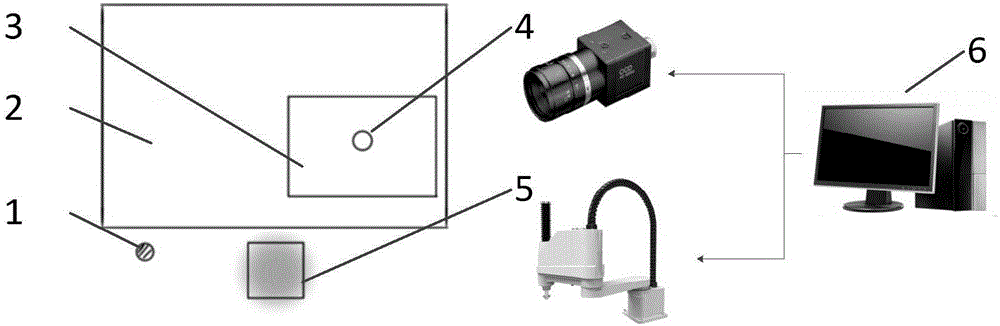
[0038] Such as figure 1 As shown, the present invention provides a fast calibration method for a robot vision system, wherein the robot vision system includes a robot 5, a work platform 2, a CCD camera 4 and a computer 6, wherein the robot 5 can use any model and needs to be able to perform high-precision positioning The CCD camera 4 has a fixed imaging lens facing the working platform 2; the computer 6 is used to control the actions of the CCD camera 4 and the robot 5; the computer 6 collects image data by the CCD camera 4, and utilizes a calibration algorithm to process the image data, At the same time, the computer 6 calculates the conversion relationship between the user coordinate system, the robot world coordinate system and the camera coordinate system by controlling the movement of the robot 5 between the marked points, and complete...


PUM


Abstract

The invention discloses a quick calibration method for a robot vision system. The robot vision system comprises a robot, a working platform, a CCD camera and a computer, wherein the computer is used for controlling the CCD camera to collect image data of the working platform, and the computer further can control movement of a robot. The method comprises the following steps of 1, mounting the CCD camera to the working platform, so that when a workpiece is put on the working platform, a local part of the workpiece is located in a view field region of the CCD camera; collecting feature coordinate points of the workpiece by coordinates of a coordinate system of the camera; 2, writing a distortion correction algorithm by utilizing opencv, and performing quick distortion correction on the CCD camera; 3, calibrating scale relations between the coordinate system of the camera and a world coordinate system of the robot and between the coordinate system of the camera and an actual size; and 4, calibrating an origin of a user coordinate system of the whole working platform. The calibration method is low in cost, convenient in installation, quick in calibration and easy to realize.

Description

technical field [0001] The invention belongs to the field of calibration of machine vision systems, in particular to a calibration method of a robot vision system with a fixed camera. Background technique [0002] Calibration is an essential step for every vision device. Now more and more automation devices are using machine vision. The accuracy and speed of calibration directly affect the production efficiency of enterprises. Now more methods are to use the early checkerboard calibration program to directly calibrate the camera, and the calibration of the robot and the camera is mostly assisted by the calibration tool, and now the camera is installed at the end of the robot arm, and the calibration tool is used for hand-eye calibration. Calibration also has a faster speed, but due to the needs of some work, it is not suitable to fix the CCD camera at the end of the robot. The robot vision system with a fixed CCD has the following defects: [0003] (1) The acquisition speed...

Claims


Application Information

Patent Timeline
Patent Type & Authority Applications(China)
IPC IPC(8): G06T7/80
Inventor 刘建春黄勇杰
Owner XIAMEN UNIV OF TECH
Why Eureka
Try Eureka