Eureka AIR delivers breakthrough ideas for toughest innovation challenges, trusted by R&D personnel around the world.

A stacked parallel mold

A mold and base mold technology, applied in the field of stacked parallel molds, can solve the problems of time-consuming and laborious replacement and installation of parallel molds, affecting cable production efficiency, and increasing the manufacturing cost of parallel molds.

Active Publication Date: 2018-05-18
LIAONING ZHONGDE CABLE CO LTD
View PDF8 Cites 1 Cited by
  • Summary
  • Abstract
  • Description
  • Claims
  • Application Information

AI Technical Summary

Problems solved by technology

Since the cabling equipment often produces cables of different specifications and models, the paralleling mold must be replaced frequently. The existing problems are: 1. Frequent replacement and installation of the paralleling mold is not only time-consuming and laborious, but also affects the production efficiency of the cable; 2. , In order to facilitate the installation of the paralleling mold on the cable forming equipment, the outer diameter of the main body is relatively fixed, only the size of the paralleling channel is different, so cables of different specifications and sizes need an outer diameter of the main body when they are cabled Parallel molds with the same size and parallel channel matching the outer diameter of the cable, which increases the manufacturing cost of the parallel mold

Method used


Image

  • A stacked parallel mold
  • A stacked parallel mold
  • A stacked parallel mold

Examples


Embodiment Construction

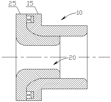
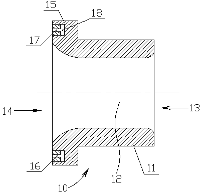
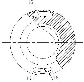
[0016] see figure 1 - Figure 6 , a stacked paralleling mold of the present invention, comprising a base mold 10, the base mold 10 has a cylindrical base mold body 11, the base mold body 11 has a base mold paralleling channel 12, and one of the base mold paralleling channels 12 One side has a basic mold paralleling line inlet 13, and the other side has a basic mold paralleling line outlet 14, and the basic mold body 11 located on one side of the basic mold paralleling line outlet 14 has a base mold peripheral vertically protruding outside the basic mold body. Along 15, a sub-mold 20 is also included. The sub-mold 20 has a cylindrical sub-mold body 21, and the sub-mold body 21 has a sub-mold paralleling channel 22, and one side of the sub-mold paralleling channel 22 has a sub-mold paralleling inlet. 23. The other side has a sub-mold doubling outlet 24, and the sub-mold body 21 on one side of the sub-mold doubling outlet 24 has a sub-mold peripheral edge 25 extending vertically...


PUM


Abstract

The invention discloses a stacked twisting mold. The stacked twisting mold comprises a basic mold which is provided with a barrel-shaped basic mold body, a basic mold twisting channel is formed in the basic mold body, one side of the basic mold twisting channel is provided with a basic mold twisting inlet, the other side of the basic mold twisting channel is provided with a basic mold twisting outlet, and the portion, located on one side of the basic mold twisting outlet, of the basic mold body is provided with a basic mold circumferential outer edge perpendicularly stretching towards the outer side of the basic mold body; the stacked twisting mold further comprises a sub-mold which is provided with a barrel-shaped sub-mold body, a sub-mold twisting channel is formed in the sub-mold body, one side of the sub-mold twisting channel is provided with a sub-mold twisting inlet, the other side of the sub-mold twisting channel is provided with a sub-mold twisting outlet, and the portion, located on one side of the sub-mold twisting outlet, of the sub-mold body is provided with a sub-mold circumferential outer edge perpendicularly stretching towards the outer side of the sub-mold body; when the sub-mold is placed in the basic mold, the outer diameter of the sub-mold body is matched with the inner diameter of the basic mold body, the sub-mold circumferential outer edge is exactly located on the basic mold circumferential outer edge, and the basic mold circumferential outer edge is provided with a locking mechanism capable of locking the sub-mold circumferential outer edge. The stacked twisting mold is convenient to replace and capable of saving time and labor.

Description

technical field [0001] The invention relates to a doubling die used for cable formation in the production process of electric cables, in particular to a stacked doubling die. Background technique [0002] In the prior art, the paralleling mold used in the cable forming process includes a cylindrical base mold body, the base mold body has a base mold paralleling channel, and one side of the base mold paralleling channel has a base mold paralleling inlet. The other side has a base mold doubling outlet, and the base mold body located on one side of the base mold doubling outlet has a base mold circumferential outer edge protruding vertically to the outside of the base mold body. When using the above-mentioned paralleling mold, it must first be fixed on the cable forming equipment. The size of the paralleling channel of the paralleling mold must match the outer diameter of the cable. If cables of different types and specifications are to be produced, the paralleling line must be...

Claims


Application Information

Patent Timeline
Patent Type & Authority Patents(China)
IPC IPC(8): H01B13/012
CPCH01B13/01209H01B13/01236
Inventor 周鑫肖扬汪洋孙百亮王福来李志强李鑫鹏
Owner LIAONING ZHONGDE CABLE CO LTD
Why Eureka
Eureka Blog
Learn More