
Varistor element with thermal protection

A varistor, overheating protection technology, applied in the direction of varistor, overvoltage protection resistor, varistor core, etc., can solve problems such as potential safety hazards, faults, equipment damage, etc.

Active Publication Date: 2018-08-17
BESTBRIGHT ELECTRONICS
View PDF4 Cites 1 Cited by
  • Summary
  • Abstract
  • Description
  • Claims
  • Application Information

AI Technical Summary

Problems solved by technology

However, since the varistor itself is connected in parallel at both ends of the protected circuit, after the varistor is disconnected from the circuit due to deterioration, it is not easy to be noticed by the user, and the surge will continue to be transmitted to the protected circuit, causing equipment damage Or cause other failures, there are potential safety hazards

Method used


Image

  • Varistor element with thermal protection
  • Varistor element with thermal protection
  • Varistor element with thermal protection

Examples


Embodiment 1

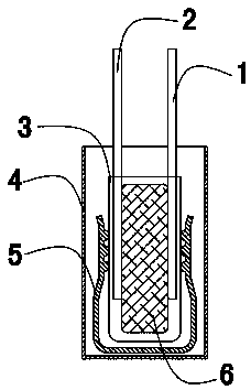
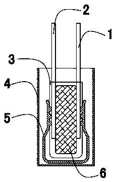
[0028] Please see figure 1 , this embodiment discloses a piezoresistive element with overheating protection, which mainly includes a first connection electrode 1 , a second connection electrode 2 , an insulating coating 3 , a casing 4 , a protection device and a piezoresistor chip 6 . In this embodiment, the electrodes on both sides of the varistor chip 6 are respectively connected to the first connecting electrode 1 and the second connecting electrode 2 . The piezoresistor chip 6 and the joints between the piezoresistor chip 6 and the first connection electrode 1 and the second connection electrode 2 are completely coated and wrapped by the insulating coating 3, and the protective device clamps the insulating coating 3 and its internal components, A conductive path exists across the protective device.

[0029] In this embodiment, the protective device is a U-shaped elastic member 5, and the two ends of the elastic member 5 correspond to the first connection electrode 1 and t...

Embodiment 2

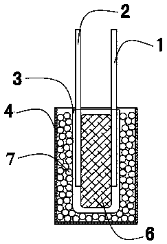
[0033] Please see image 3 , this embodiment discloses a piezoresistive element with overheating protection, which mainly includes a first connection electrode 1 , a second connection electrode 2 , an insulating coating 3 , a casing 4 , conductive particles 7 and a piezoresistor chip 6 . In this embodiment, the electrodes on both sides of the piezoresistor chip 6 are connected to the first connection electrode 1 and the second connection electrode 2 respectively, and the piezoresistor chip 6 and the piezoresistor chip 6 are connected to the first connection electrode 1 and the second connection electrode 2 respectively. The junction of the connection electrode 2 is completely coated with an insulating coating 3 . The varistor chip is placed in the casing 4, and the inside of the casing 4 is filled with conductive particles 7, and the conductive particles 7 are closely attached to the insulating coating.

[0034] When the piezoresistor chip 6 begins to deteriorate, the heat ge...


PUM


Abstract

The invention discloses a voltage-sensitive resistor element with overheat protection, and relates to the technical field of basic electronic elements. The resistor element comprises a voltage-sensitive resistor chip, wherein a first connecting electrode and a second connecting electrode electrically connected with an electrode of the chip are arranged on a surface of the chip; the entirety of the chip and connection parts of the connecting electrodes and the chip are wrapped by an insulation coating; a protection device is arranged outside the insulation coating; a combined chip composed of the protection device, the voltage-sensitive resistor chip and the connecting electrodes is located in a housing; free ends of the connecting electrodes are located outside the housing. A short circuit shunt pathway is present in the resistor element; the presence of the short circuit shunt pathway releases surge current, which can protect a rear-end circuit from influence of surge when a voltage-sensitive resistor is degraded and failed; the short circuit current is easily detected by a front-end current fuse and other devices, so as to power off the complete machine equipment timely and avoid further damage.

Description

technical field [0001] The invention relates to the technical field of basic electronic components, in particular to a piezoresistive element with overheat protection. Background technique [0002] The varistor is a voltage-limiting protection device with strong surge absorption capability and is widely used in electronic circuits. It mainly uses the non-linear characteristics of the varistor to clamp the voltage when the voltage is overvoltage and absorb the excess current, so as to realize the protection of the subsequent circuit. [0003] The varistor will gradually deteriorate as the number of times of surge absorption increases, causing the current flowing through the varistor to continue to increase and the temperature to continue to rise, which may eventually cause the product to explode or catch fire. [0004] In order to avoid serious consequences caused by the deterioration of the varistor, it is necessary to protect the varistor from overheating. At present, ther...

Claims


Application Information

Patent Timeline
Patent Type & Authority Patents(China)
IPC IPC(8): H01C7/105H01C7/12
CPCH01C7/105H01C7/12
Inventor 周云福张晗
Owner BESTBRIGHT ELECTRONICS
Learn More