Space columnar paraboloid thin plate antenna based on inflatable structure

An inflatable structure, paraboloid technology, applied in the field of spacecraft structure, can solve problems such as inability to meet, and achieve the effects of large storage ratio, reduced power consumption requirements, good processing technology and assembly technology

Inactive Publication Date: 2017-05-31
SHANGHAI SATELLITE ENG INST
View PDF6 Cites 5 Cited by
  • Summary
  • Abstract
  • Description
  • Claims
  • Application Information

AI Technical Summary

Problems solved by technology

Therefore, conventional antenna retractable configura

Method used


Image

  • Space columnar paraboloid thin plate antenna based on inflatable structure
  • Space columnar paraboloid thin plate antenna based on inflatable structure

Examples


Embodiment Construction

[0010] The present invention will be described in detail below in conjunction with specific embodiments. The following examples will help those skilled in the art to further understand the present invention, but do not limit the present invention in any form. It should be noted that those skilled in the art can make several modifications and improvements without departing from the concept of the present invention. These all belong to the protection scope of the present invention.

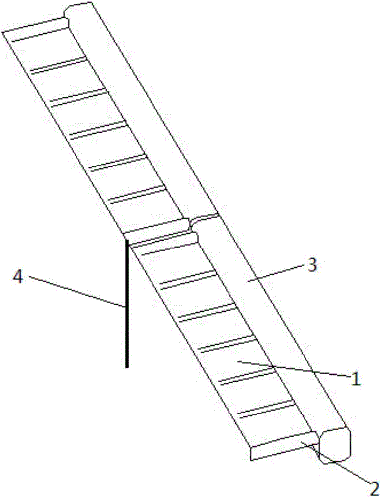
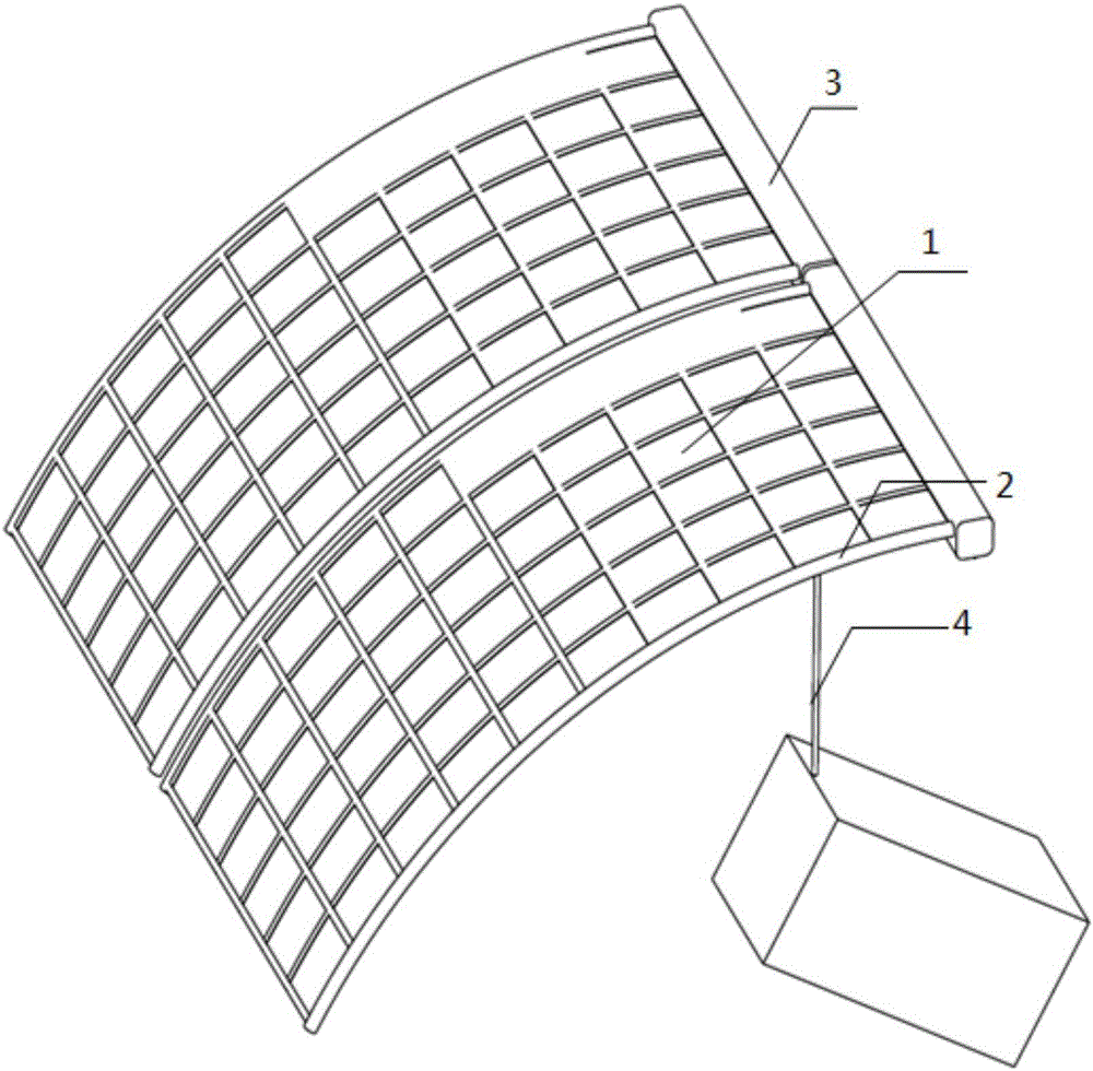
[0011] Such as Figure 1-Figure 2 As shown, the embodiment of the present invention provides a space columnar parabolic thin plate antenna based on an inflatable structure, including a thin plate antenna 1, an inflatable structure 2, a storage tube 3 and a support arm 4, and the thin plate antenna 1 is fixedly connected to the inflatable structure 2 and then folded in On the storage tube 3, the inflatable structure is inflated to expand its volume and stretch outward, thereby driving the entire me...


PUM


Abstract

The invention discloses a space columnar paraboloid thin plate antenna based on an inflatable structure. The antenna comprises a thin plate antenna, the inflatable structure, a storage tube and a support arm. The thin plate antenna is fixedly connected with the inflatable structure and is folded on the storage tube. The support arm is arranged on the lower end of the inflatable structure. According to the invention, the antenna has the advantages of simple design construction and good processing manufacturability and assembling manufacturability; the thin plate antenna construction is used; deformation energy is stored in a folded state; deformation energy is released in an unfolding process; the power consumption demand of a drive device is reduced; the antenna has the characteristics of large storage capacity and light weight; the inflatable structure is used; the inflatable structure is inflated to unfold the entire antenna surface; the unfolding surface of the antenna is ensured; and the unfolding stiffness of the antenna surface is improved.

Description

technical field [0001] The invention relates to the technical field of spacecraft structures, in particular to a space columnar parabolic thin-plate antenna based on an air-filled structure. Background technique [0002] In order to solve the contradiction between the large-area antenna array of the spacecraft and the size limit of the carrying envelope, the spacecraft needs to gather the antenna on the star during the active launch phase, and unfold and lock the antenna to the working state after entering orbit. At the same time, on the basis of meeting the requirements for antenna use, satellites have increasingly stringent requirements for the lightweight antenna structure, and put forward higher requirements for the envelope, storage ratio and weight of the extension device. Therefore, conventional antenna deployment and retraction configuration design can no longer meet the above various requirements. Contents of the invention [0003] In order to solve the above tec...

Claims


Application Information

Patent Timeline
IPC IPC(8): H01Q1/08H01Q1/28
CPCH01Q1/288H01Q1/081
Inventor 袁野杜三虎王萌王智磊赵枝凯
Owner SHANGHAI SATELLITE ENG INST
Why Eureka
Try Eureka