

Splicing type combined power distribution cabinet
A power distribution cabinet and splicing technology, which is applied in the field of splicing combined power distribution cabinets, can solve the problems of great safety, hidden dangers, and indispensable electrical control cabinets.
- Summary
- Abstract
- Description
- Claims
- Application Information
AI Technical Summary
Problems solved by technology
Method used
Image

Examples
Embodiment 1
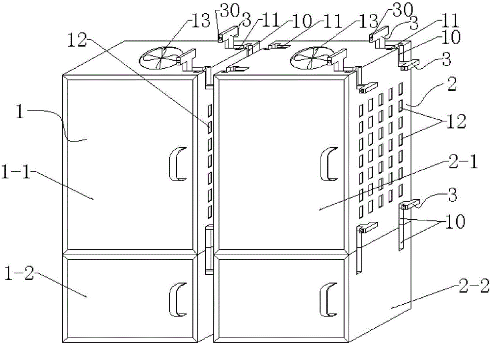
[0022] First place the lower box body 1-2 of the first cabinet 1, then place the upper box body 1-1 directly above the lower box body 1-2, and then use the connecting block 3 to pass the upper box body 1-1- The horizontal groove 11 of 1 and the horizontal groove 11 on the lower casing one 1-2 connect the upper casing one 1-1 and the lower casing one 1-2 together, and then the lower casing two of the second cabinet 2 2-2 is placed well, and there is a certain distance between the upper box body 1-1 and the upper box body 1-1, and then the connecting block 3 passes through the vertical groove 10 on the lower box body 1-2 and the lower box body 2 2-2. The vertical slot 10 of the lower casing one 1-2 and the lower casing two 2-2 are connected together, then the upper casing two 2-1 is placed on the lower casing two 2-2 directly above, and then with the connecting block 3 The lower casing two 2-2 and the upper casing two 2-1 are connected together by the horizontal groove 11 on the...
Embodiment 2
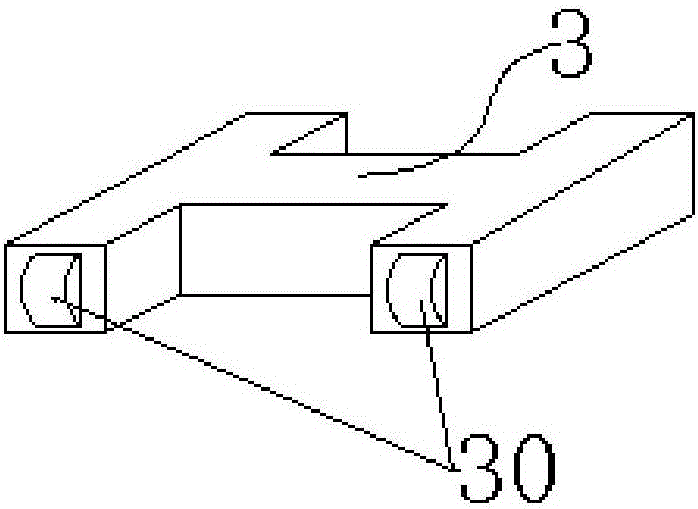
[0024] Connect the first cabinet 1 and the second cabinet 2 with "work" blocks, so that there is a gap between the first cabinet 1 and the second cabinet 2, and the "work" blocks are provided with four rollers 30, Ensure that the connection block 3 is installed into the vertical groove 10 and the simplicity of the horizontal groove 11, and a heat dissipation window 12 is provided on the right side of the upper box 1-1, and on the left and right sides of the upper box 2 2-1 All are provided with heat dissipation windows 12, in addition, a cooling fan 13 is provided in the middle of the top of the upper box body 1-1, and a cooling fan 13 is arranged in the middle of the top of the upper box body 2-1, through the exhaust effect and heat dissipation of the cooling fan 13 The heat dissipation function of the window 12 makes the heat dissipation performance of the entire power distribution cabinet excellent, effectively avoiding the potential safety hazards of high internal temperatu...
PUM
 Abstract
Description
Claims
Application Information