
a bleeder circuit

A discharge circuit and discharge technology, applied in the field of electronics, can solve the problems of time-consuming discharge of discharge energy at a certain speed, waste of resources, and lack of intelligence, and achieve the effect of reducing heat generation and adjustable discharge time.

Active Publication Date: 2019-07-12
WEIHAI NEWBEIYANG ZHENGQI ROBOT
View PDF4 Cites 1 Cited by
  • Summary
  • Abstract
  • Description
  • Claims
  • Application Information

AI Technical Summary

Problems solved by technology

[0003] In view of this, the purpose of the embodiments of the present invention is to provide a discharge circuit to improve the waste of resources, time-consuming and fixed speed of discharging electric energy in the prior art, which is not intelligent enough.

Method used


Image

  • a bleeder circuit
  • a bleeder circuit
  • a bleeder circuit

Examples


Embodiment Construction

[0013] In order to make the purpose, technical solutions and advantages of the embodiments of the present invention clearer, the technical solutions in the embodiments of the present invention will be clearly and completely described below in conjunction with the drawings in the embodiments of the present invention. Obviously, the described embodiments It is a part of embodiments of the present invention, but not all embodiments. The components of the embodiments of the invention generally described and illustrated in the figures herein may be arranged and designed in a variety of different configurations.

[0014] Accordingly, the following detailed description of the embodiments of the invention provided in the accompanying drawings is not intended to limit the scope of the claimed invention, but merely represents selected embodiments of the invention. Based on the embodiments of the present invention, all other embodiments obtained by persons of ordinary skill in the art wi...


PUM


Abstract

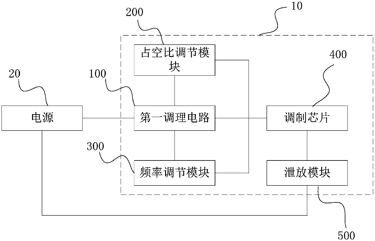
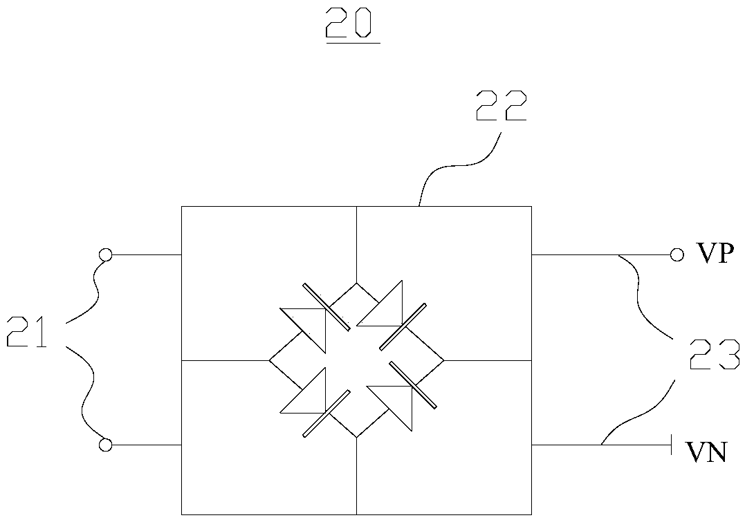
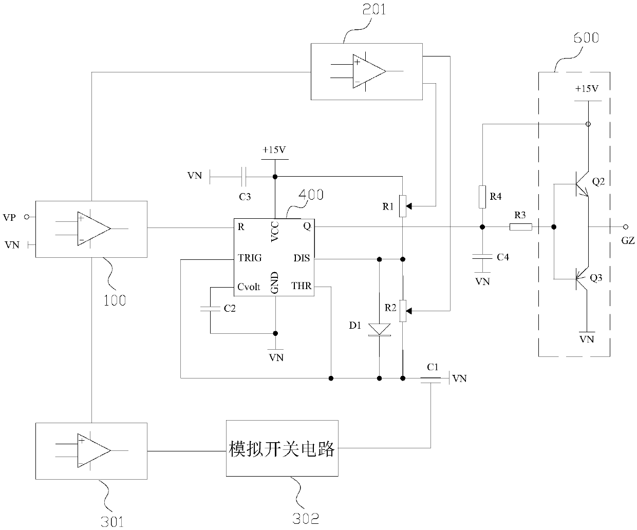
The embodiment of the invention provides a bleeder circuit, and relates to the technical field of electron. The bleeder circuit comprises a first modulation circuit, a duty cycle adjustment module, a frequency adjustment module, a modulation chip and a bleeder module. The first modulation circuit, the duty cycle adjustment module, the frequency adjustment module and the bleeder module are all connected to the modulation chip, and the duty cycle adjustment module and the frequency adjustment module are further connected to the first modulation circuit. Whether a voltage of a power source exceeds an overvoltage set value or not is detected through the first modulation circuit, a PWM signal is generated by controlling the modulation chip, and according to the voltage, which exceeds the overvoltage set value, of the power source, the duty cycle modulation module and the frequency adjustment module adjust the duty cycle and the frequency of the PWM signal output by the modulation chip respectively to further achieve the work time of the bleeder module and to achieve the purpose of electric energy release of the power source. According to the bleeder circuit, the resource of an MCU and software resources can be not occupied, time and labor are saved, moreover, the bleeder resistor is connected when the electric energy is bled, and unnecessary heating of devices is reduced.

Description

technical field [0001] The present invention relates to the field of electronic technology, in particular to a discharge circuit. Background technique [0002] At present, the solution to the excessive voltage of the busbar is to use a bleeder circuit, which is a circuit that deliberately consumes a part of energy and converts it into heat or other forms of energy. There are two ways to realize the traditional bleeder circuit: the first way is to implement it through hardware. After detecting that the DC bus has reached the overvoltage setting value through a part of the control and conditioning circuit, the DC bus voltage is directly connected to the bleeder resistor. Energy consumption; there is also a discharge circuit controlled by a time-base chip, but the speed of discharging energy is certain and not smart enough. The second method is implemented by software. The MCU constantly detects the bus voltage and controls the frequency of the discharge through software, whic...

Claims


Application Information

Patent Timeline
Patent Type & Authority Patents(China)
IPC IPC(8): H02J5/00
CPCH02J5/00
Inventor 秦健强李强林建琳姚庭
Owner WEIHAI NEWBEIYANG ZHENGQI ROBOT
Learn More