
Adjusting type automatic feeding device for metal pipe machining

An automatic feeding and adjusting technology, which is applied in the direction of metal processing equipment, conveyors, manufacturing tools, etc., can solve the problems of aggravating the labor burden of the staff, increasing the workload of the staff, scratching the hands of the staff, etc., and achieve the improvement The effect of automation, increased residence time, and easy operation

Pending Publication Date: 2022-02-08
陈东鑫
View PDF8 Cites 0 Cited by
  • Summary
  • Abstract
  • Description
  • Claims
  • Application Information

AI Technical Summary

Problems solved by technology

[0004] The purpose of the present invention is to provide an adjustable automatic feeding device for metal pipe processing to solve the problem that metal pipes generally have special derusting machines for mechanical grinding and derusting. Push it to the grinding wheel for grinding, but the current pipeline derusting device is manually loaded, which not only increases the workload of the staff, but also easily produces corrosion when the pipeline with rust is machined. Vibration can easily cause scratches on the hands of the staff. In addition, the inlet and outlet of some small rust removal devices are the same, and the loading and unloading of materials requires the assistance of staff, which undoubtedly aggravates the labor burden of the staff.

Method used


Image

  • Adjusting type automatic feeding device for metal pipe machining
  • Adjusting type automatic feeding device for metal pipe machining
  • Adjusting type automatic feeding device for metal pipe machining

Examples


Embodiment Construction

[0032] The following will clearly and completely describe the technical solutions in the embodiments of the present invention with reference to the accompanying drawings in the embodiments of the present invention. Obviously, the described embodiments are only some, not all, embodiments of the present invention. Based on the embodiments of the present invention, all other embodiments obtained by persons of ordinary skill in the art without making creative efforts belong to the protection scope of the present invention.

[0033] see Figure 1-9 , an embodiment provided by the present invention:

[0034] An adjustable automatic feeding device for metal pipe processing, comprising:

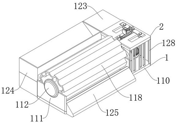
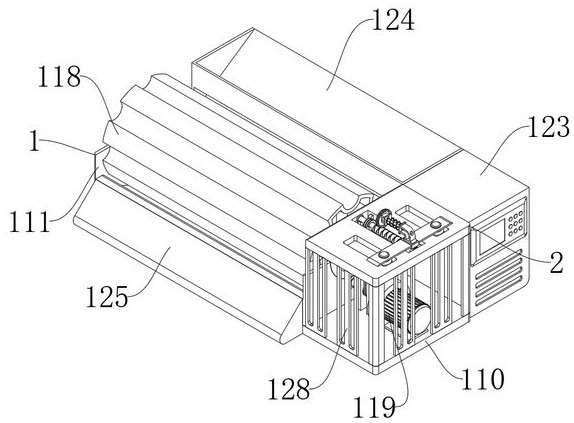
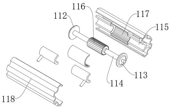
[0035] The device main body 1, the device main body 1 includes a base plate 110, a bracket cover 111 is fixedly installed on one end of the base plate 110, a positioning disc 112 is embedded in the bracket cover 111, and a moving position disc 113 is embedded in the bracket cover 111 on one side of ...


PUM


Abstract

The invention relates to the technical field of metal pipe feeding, in particular to an adjustable automatic feeding device for metal pipe machining. The device comprises a device body and a rotating shaft; the device body comprises a bottom plate, a support sleeve is fixedly mounted at one end of the bottom plate, a positioning disc is mounted on the support sleeve in an embedded manner, and a movable disc is mounted on the support sleeve on one side of the positioning disc in an embedded manner; and the rotating shaft is movably connected to the movable disc in a sleeving manner through a bearing. According to the invention, the servo motor, the rotating shaft, a feeding sleeve and a funnel sleeve are arranged, the servo motor is used for driving the rotating shaft to rotate so as to drive the feeding sleeve to rotate, then a metal pipe in the funnel sleeve can gradually enter a pipe placing groove in the feeding sleeve, and therefore automatic pipe loading and feeding are conducted; and a derusting device is arranged at the same position of an inlet and an opening, so that the residence time of the feeding sleeve can be prolonged, and the supporting effect of feeding and discharging of the pipe containing groove is achieved.

Description

technical field [0001] The invention relates to the technical field of metal pipe feeding, in particular to an adjustable automatic feeding device for metal pipe processing. Background technique [0002] Metal pipes generally need to be derusted after long-term storage. Derusting uses chemical, electrochemical, mechanical and other methods to remove oxides on the surface of equipment and its parts. Commonly used derusting methods include chemical derusting, electrochemical derusting, sand blasting, manual derusting and rolling derusting. Chemical derusting, electrochemical derusting and manual derusting, etc., use hand tools and motorized hand tools to remove the rust layer on the surface of parts through mechanical cutting. Rust removal is widely used in equipment maintenance, repair and surface pretreatment. For example, before the deck surface of a ship is repainted, manual rust removal or sandblasting is usually used; before arc spraying and other technologies are appl...

Claims


Application Information

Patent Timeline
IPC IPC(8): B65G47/18B65G47/74B24B27/033B24B41/00
CPCB65G47/18B65G47/74B24B27/033B24B41/005B65G2201/0276
Inventor 陈东鑫
Owner 陈东鑫
Learn More