
Battery pack charge-discharge control circuit and electrocar power battery system

A charge and discharge control and control circuit technology, applied in battery circuit devices, electric vehicle charging technology, electric vehicles, etc., can solve the problem of short life of power batteries, and achieve the purpose of improving service life, reducing decay speed, and eliminating potential safety hazards. Effect

Pending Publication Date: 2017-05-31
祁国俊
View PDF9 Cites 17 Cited by
  • Summary
  • Abstract
  • Description
  • Claims
  • Application Information

AI Technical Summary

Problems solved by technology

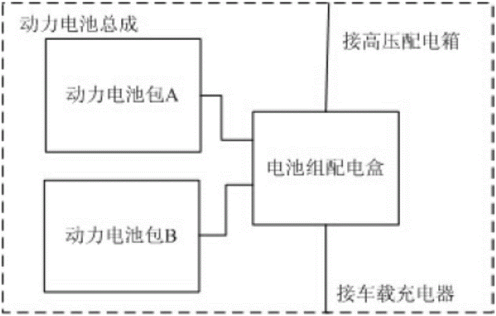
[0006] The purpose of the present invention is to provide a battery pack charging and discharging control circuit and electric vehicle power battery system to solve the technical problem of short power battery life in the prior art when parallel battery packs are used in the power battery system

Method used


Image

  • Battery pack charge-discharge control circuit and electrocar power battery system
  • Battery pack charge-discharge control circuit and electrocar power battery system
  • Battery pack charge-discharge control circuit and electrocar power battery system

Examples


no. 1 example

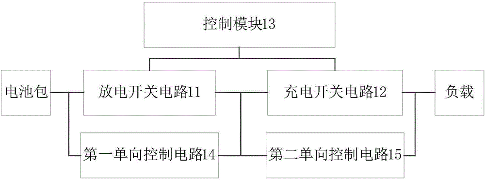
[0032] figure 2 The structural block diagram of the battery pack charge and discharge control circuit provided in the first embodiment of the present application. The battery pack charge and discharge control circuit provided in this embodiment is applied to the electric vehicle power battery system. A battery pack charge and discharge control circuit pair has multiple The charging and discharging of a battery pack in the power battery system with parallel battery packs is controlled, specifically, as figure 2 As shown, the battery pack charge and discharge control circuit includes a discharge switch circuit 11 , a charge switch circuit 12 , a control module 13 , a first one-way control circuit 14 and a second one-way control circuit 15 .

[0033]The discharge switch circuit 11 is used to turn on when the battery pack is discharged, and to turn off when the battery pack is charged; the charging switch circuit 12 is used to be turned on when the battery pack is charged, and t...

no. 2 example

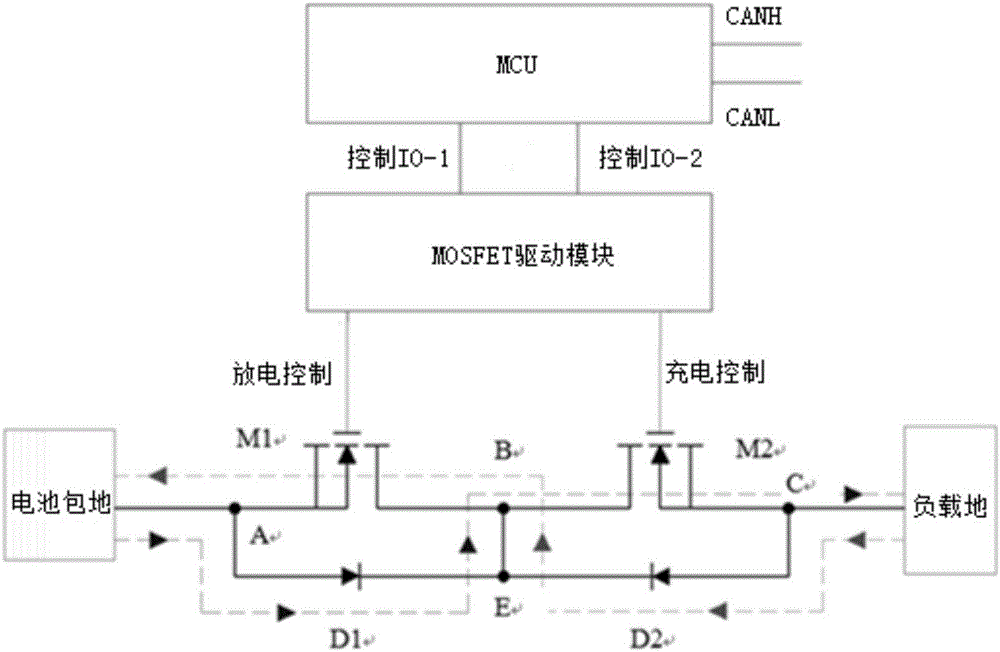
[0044] image 3 It is the circuit principle diagram of the battery pack charge and discharge control circuit provided in the second embodiment of the present application. The battery pack charge and discharge control circuit provided in this embodiment is applied to the electric vehicle power battery system. A battery pack charge and discharge control circuit pair has multiple Control the charge and discharge of one battery pack in the power battery system of four parallel battery packs, specifically, such as image 3 As shown, the battery pack charge and discharge control circuit includes an MCU, a MOSFET drive module, a first MOSFET tube M1, a second MOSFET tube M2, a first diode D1, and a second diode D2. It should be noted that this implementation The examples only illustrate the electronic components included in the circuit, and are not intended to limit the specific circuit composition of the battery pack charging and discharging control circuit of the present applicatio...

no. 3 example

[0054] Figure 4 The structural block diagram of the electric vehicle power battery system provided by the third embodiment of the present application includes a plurality of battery packs 20 , a plurality of control circuits 10 , a plurality of collectors 30 and a control unit 40 .

[0055] Wherein, multiple battery packs 20 are connected in parallel in the power battery system, and each battery pack includes multiple single batteries connected in series and / or in parallel. Each control circuit 10 is connected in series with a battery pack 20, and each control circuit 10 controls the charging and discharging state of the battery pack 20 connected in series with itself. The control circuit will not be described in detail here. Each collector 30 is connected to a battery pack 20 for collecting working parameters of a battery pack 20 , including parameters such as voltage, current and temperature of the battery pack 20 . The control unit 40, as the general control part of the ...


PUM


Abstract

The invention discloses a battery pack charge-discharge control circuit and an electrocar power battery system. The control circuit comprises a discharge switch circuit, a charge switch circuit, a first unidirectional control circuit and a second unidirectional control circuit, wherein the discharge switch circuit is conducted when the battery pack is in discharge and is turned off when the battery pack is in charge; the charge switch circuit is conducted when the battery pack is in charge and is turned off when the battery pack is in discharge; the control module is used for controlling the on-off states of the discharge switch circuit and the charge switch circuit; the first unidirectional control circuit is connected to the discharge switch circuit in parallel, and the direction of the electric current passing through the first unidirectional control circuit is reverse to the direction of the electric current passing through the discharge switch circuit; the second unidirectional control circuit is connected to the charge switch circuit in parallel, and the direction of the electric current passing through the second unidirectional control circuit is reverse to the direction of the electric current passing through the charge current circuit. According to the battery pack charge-discharge control circuit and the electrocar power battery system, multiple battery packs are included, the problems of self charge and self discharge of power batteries can be avoided, the decay rate of the power batteries is reduced, and the service life of the whole electrocar is improved.

Description

technical field [0001] The invention relates to the technical field of power batteries, in particular to a battery pack charging and discharging control circuit and an electric vehicle power battery system. Background technique [0002] Power batteries refer to batteries that provide power for transportation vehicles, generally compared to small batteries that provide energy for portable electronic devices, such as batteries that provide power for electric vehicles, electric trains, electric bicycles, and golf carts. According to different battery reaction principles, it can be divided into lead-acid power battery, nickel-metal hydride power battery, lithium-ion power battery and so on. [0003] No matter what kind of power battery is used, in order to improve the cruising range of electric vehicles, the technology of connecting multiple battery packs in series is usually used. At present, most of the power batteries of electric vehicles on the market use parallel packaging ...

Claims


Application Information

Patent Timeline
Patent Type & Authority Applications(China)
IPC IPC(8): H02J7/00B60L11/18
CPCH02J7/00H02J7/0013B60L53/00Y02T10/70Y02T10/7072Y02T90/14
Inventor 祁国俊黎明南
Owner 祁国俊
Learn More