Charging method, charger and mobile terminal
A mobile terminal and charger technology, applied in the field of communication, can solve problems such as corrosion and oxidation of USB connectors
- Summary
- Abstract
- Description
- Claims
- Application Information
AI Technical Summary
Problems solved by technology
Method used
Image

Examples
no. 1 example
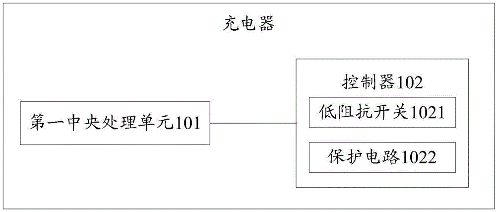
[0026] see figure 1 , figure 1 is a structural diagram of a charger provided by an embodiment of the present invention, such as figure 1 As shown, the charger includes a first central processing unit 101 and a controller 102, wherein:
[0027] The first central processing unit 101 is configured to detect whether a power-off instruction sent by the mobile terminal is received, and output a first control signal to the controller 102 if the power-off instruction is detected.
[0028] The first central processing unit 101 is connected to the controller 102 . The mobile terminal will monitor the state of the battery pack in real time, and when it detects that the charging of the battery pack is complete, the mobile terminal will send a power-off command to the first central processing unit 101 of the charger, and the first central processing unit 101 of the charger receives this After the power-off command, a first control signal will be sent to the controller 102 .
[0029] Th...
no. 2 example
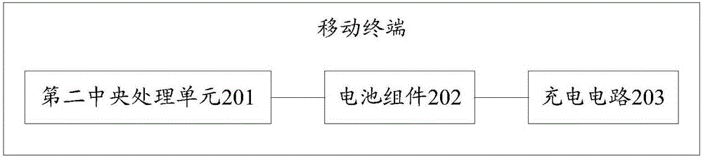
[0046] see figure 2 , figure 2 is a structural diagram of a mobile terminal provided by an embodiment of the present invention, such as figure 2 As shown, the mobile terminal includes a second central processing unit 201 and a battery pack 202, wherein:
[0047] If the mobile terminal has established a connection with the charger, the second central processing unit 201 detects whether the voltage of the battery assembly 202 is higher than a preset first threshold, and if it detects that the voltage of the battery assembly 202 is higher than The preset first threshold value sends a power-off instruction to the charger, so that the charger stops outputting the charging voltage according to the power-off instruction.
[0048] The second central processing unit 201 is connected to the battery pack 202 . The second central processing unit 201 of the mobile terminal will monitor the status of the battery pack 202 in real time, and when it is detected that the voltage of the ba...
no. 3 example
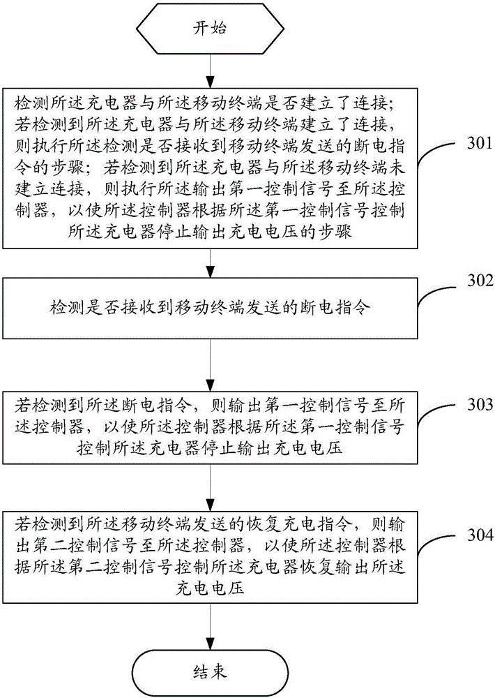
[0054] see image 3 , image 3 is a flowchart of a charging method provided by an embodiment of the present invention, which is applied to a charger, and the charger includes a controller, such as image 3 shown, including the following steps:
[0055] Step 301: Detect whether the charger has established a connection with the mobile terminal; if it is detected that the charger has established a connection with the mobile terminal, perform the detection of whether a power-off instruction sent by the mobile terminal is received Step: If it is detected that the charger has not established a connection with the mobile terminal, then perform the output of the first control signal to the controller, so that the controller controls the charging according to the first control signal The step in which the converter stops outputting the charging voltage.
[0056] In step 301, if Figure 4 Shown is a schematic diagram of a charger charging a mobile terminal. exist Figure 4 Among t...
PUM
 Abstract
Description
Claims
Application Information
 - R&D
- Intellectual Property
- Life Sciences
- Materials
- Tech Scout
- Unparalleled Data Quality
- Higher Quality Content
- 60% Fewer Hallucinations
Browse by: Latest US Patents, China's latest patents, Technical Efficacy Thesaurus, Application Domain, Technology Topic, Popular Technical Reports.
© 2025 PatSnap. All rights reserved.Legal|Privacy policy|Modern Slavery Act Transparency Statement|Sitemap|About US| Contact US: help@patsnap.com