Rectangular-ambulatory-plane oil sealing structure of steam turbine generator

A turbo-generator and sealing structure technology, which is applied to electrical components, electromechanical devices, electric components, etc., can solve the problems of increasing application costs, incomplete sealing paths, and greatly increasing the amount of hydrogen supplemented by turbo-generators. The effect of reducing the amount of hydrogen supplementation, reducing the application cost and improving the reliability of safe operation

Active Publication Date: 2017-05-31
DONGFANG ELECTRIC MACHINERY
View PDF5 Cites 5 Cited by
  • Summary
  • Abstract
  • Description
  • Claims
  • Application Information

AI Technical Summary

Problems solved by technology

[0003] The current turbo-generator mainly adopts single-flow ring, double-flow ring or three-flow ring sealing structure. This kind of sealing structure mainly has the defect that the sealing path is not completely closed during the working process of the turbo-generator, especially on its horizontal joint surface. It cannot fully ensure the effective barrier between the inner hydrogen side (high pressure area) of the turbogenerator and the outer side (low pressure area), so that part of the hydrogen can flow from the inner hydrogen side (high pressure area) of the turbogenerator to the outer side of the machine. (low pressure area), resulting in defects such as air leakage and oil leakage when the turbo-generator is working, especially at the horizontal joint surface, oil leakage occurs more frequently
During the working process of the turbogenerator, if defects such as air leakage and oil leakage occur, it will directly lead to a large increase in the amount of hydrogen supplemented by the turbogenerator, and correspondingly increase the application cost

Method used


Image

  • Rectangular-ambulatory-plane oil sealing structure of steam turbine generator
  • Rectangular-ambulatory-plane oil sealing structure of steam turbine generator

Examples


Embodiment Construction

[0016] In order to make the object, technical solution and advantages of the present invention clearer, the present invention will be described in detail below in conjunction with the accompanying drawings and specific embodiments. It should be understood that the specific embodiments described here are only used to explain the present invention, not to limit the present invention.

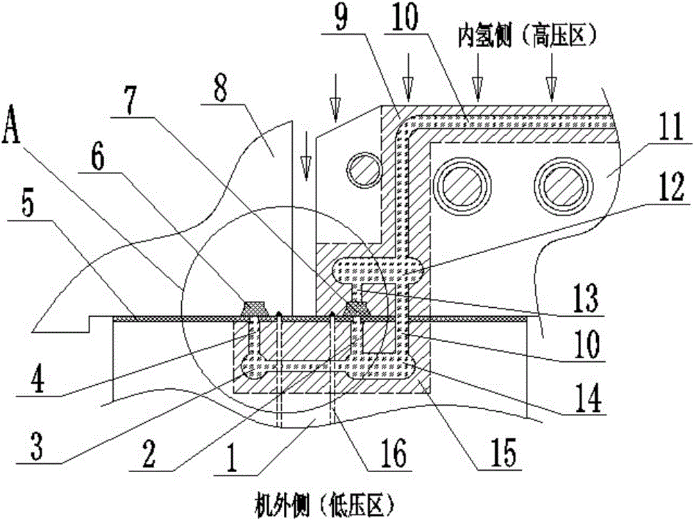
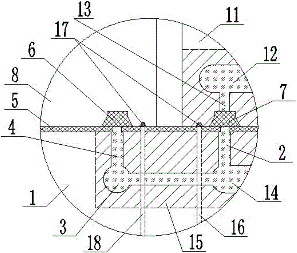
[0017] Such as figure 1 , figure 2 A turbogenerator "back" shaped oil seal structure shown mainly includes a transition ring 1, an end cover 8 and a sealing seat 11, and the transition ring 1 is formed with the end cover 8 and the sealing seat 11 through a sealing plate 5 respectively. The sealing structure, wherein the transition ring 1 and the end cover 8, and the seal seat 11 and the transition ring 1 can be fixed by bolts respectively, and the bolts pass through the sealing plate 5, the sealing plate 5 is preferably a rubber plate, usually , is to directly bond the sealing plate 5 to the tr...


PUM


Abstract

The invention provides a rectangular-ambulatory-plane oil sealing structure of a steam turbine generator. The rectangular-ambulatory-plane oil sealing structure comprises a transition ring, an end cover and a sealing seat, wherein the transition ring forms sealing structures respectively with the end cover and the sealing seat by a sealing plate, a first branch oil passage and a second branch oil passage are formed in the transition ring and communicate with each other, the first branch oil passage and the second branch oil passage respectively penetrates through the sealing plate, an installation groove is formed in the end cover, a second sealing strip is embedded into the installation groove, an installation groove is formed in the sealing seat, a first sealing strip is embedded into the installation groove, the first branch oil passage and the second branch oil passage are filled with sealing oil, and the first branch oil passage, the second branch oil passage, the sealing plate, the second sealing strip and the first sealing strip jointly form the rectangular-ambulatory-plane oil sealing structure. By the rectangular-ambulatory-plane oil sealing structure, the hydrogen supplement quantity during running of the steam turbine generator can be greatly reduced, the application cost of the steam turbine generator is reduced, and the running safety and reliability of the steam turbine generator can be effectively improved.

Description

technical field [0001] The invention relates to the technical field of seal structure design of a turbo-generator, in particular to a "back"-shaped oil sealing structure of a turbo-generator. Background technique [0002] The main heat exchange component of the turbogenerator is a hydrogen cooler (referred to as "hydrogen cooler", the same below), and the cooling medium in it is hydrogen. Since hydrogen is the lightest gas, its permeability and diffusivity are very strong, it is easy to cause hydrogen leakage in a pressure vessel filled with hydrogen. As the amount of hydrogen leakage continues to increase, it will affect the output of the turbogenerator, and even cause an explosion, resulting in a safety accident. Therefore, the operating turbogenerator has strict requirements on the amount of hydrogen leakage. [0003] The current turbo-generator mainly adopts single-flow ring, double-flow ring or three-flow ring sealing structure. This kind of sealing structure mainly ha...

Claims


Application Information

Patent Timeline
Patent Type & Authority Applications(China)
IPC IPC(8): H02K5/10
CPCH02K5/10H02K5/12Y02E10/20H02K9/02
Inventor 官永胜陈文学胡德剑朱林重秦川
Owner DONGFANG ELECTRIC MACHINERY
Why Eureka
Try Eureka