Brush positioning method for single-wave winding permanent magnet DC motor based on the second pitch

A single-wave winding and positioning method technology, which is applied in the direction of electromechanical devices, manufacturing motor generators, electrical components, etc., can solve the problem of brush position changes, differences, and inability to clearly express the relationship between magnetic steel stators, brushes and coil components, etc. problem, to achieve the effect of clear thinking and wide application range

Active Publication Date: 2019-08-09
BEIJING PULIMEN ELECTRO MECHANICAL HIGH TECHN CO
View PDF2 Cites 0 Cited by
  • Summary
  • Abstract
  • Description
  • Claims
  • Application Information

AI Technical Summary

Problems solved by technology

This method gives the theoretical position of the brush from the commutation theory, but does not give the steps and methods of specific positioning, and thus cannot give the specific brush position intuitively, which will be different due to different understanding methods of designers; secondly, the method The theory only analyzes the position of the brush in general, without further analyzing the diversity of the connection between the rotor element and the commutator segment in detail, which will bring great changes to the determination of the position of the brush
Therefore, the current theoretical method cannot be close to the actual engineering, and cannot clearly express the relationship between the magnetic steel stator, the brush and the coil components, and the positioning of the brush is not clear.

Method used


Image

  • Brush positioning method for single-wave winding permanent magnet DC motor based on the second pitch
  • Brush positioning method for single-wave winding permanent magnet DC motor based on the second pitch
  • Brush positioning method for single-wave winding permanent magnet DC motor based on the second pitch

Examples


Embodiment Construction

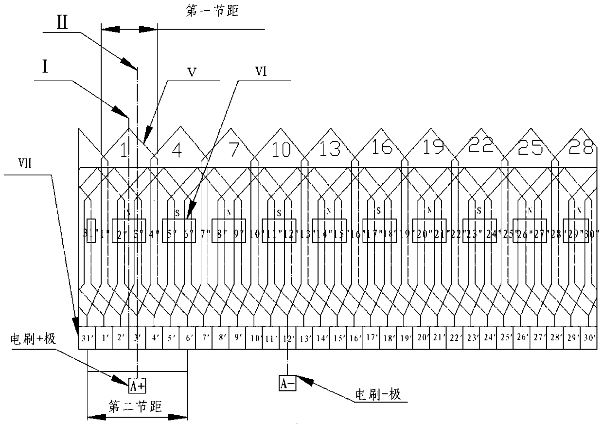
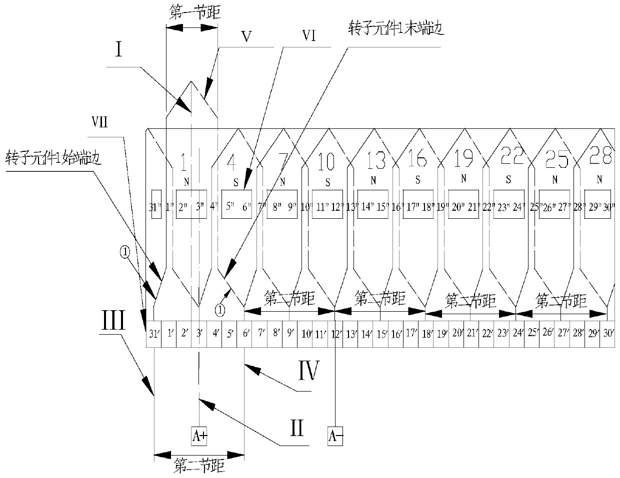
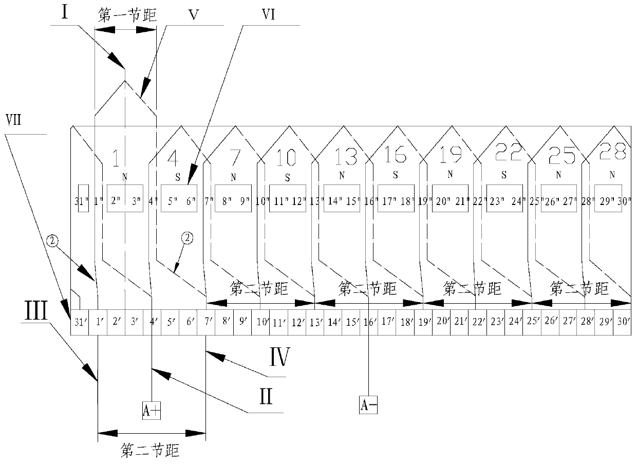
[0016] The present invention will be described in further detail below in conjunction with the accompanying drawings. First, the symbolic representations in each figure will be explained. figure 1 , figure 2 and image 3 Ⅴ in the figure represents the rotor element, Ⅵ represents the stator magnet, and Ⅶ represents the commutator segment.

[0017] A method for positioning a brush of a permanent magnet DC motor with a single-wave winding based on a second pitch, the method comprising the following steps:

[0018] Step 1: Select the moment when the potential of the rotor element of the single-wave winding permanent magnet DC motor is the largest and the current is zero, and establish the time expansion diagram of the stator magnet, rotor element and commutator at this time, and determine the rotor element in the time expansion diagram For all the rotor elements whose axis coincides with the axis of each stator magnetic steel, the start end and end edge of each rotor element i...


PUM


Abstract

The invention discloses a method for positioning an electric brush of a single-wave winding permanent magnet direct current motor based on second pitches. The method comprises the following steps: 1, selecting a moment when rotor components of the single-wave winding permanent magnet direct current motor have largest potential and zero current, establishing a moment expanded view of stator magnetic steel, the rotor components and commutator segments at the moment, determining all the rotor components, of which the axes are superposed with the axis of each piece of stator magnetic steel, in the moment expanded view, connecting the starting end edge and the tail end edge of each rotor component in all the rotor components with the two commutator segments correspondingly; and 2, determining the center line of each second pitch, taking the center line position as the mounting position of one pole of the electric brush, and mounting the other pole of the electric pole by rotating 180-degree electrical angle position based on the mounting position of one pole of the electric brush. By the method, all the positions of the electric brush of the single-wave winding permanent magnet direct current motor can be positioned, and the method is simple, convenient and intuitive.

Description

technical field [0001] The invention relates to the technical field of design of permanent magnet brushed direct current motors, in particular to a brush positioning method for single wave winding permanent magnet direct current motors based on the second pitch. Background technique [0002] At present, the brush positioning method for single-wave winding permanent magnet DC motors is mainly based on the positioning method of the magnetic pole axis. When the axis of the motor rotor element coincides with the axis of the magnetic steel, the magnetic potential of the rotor element is the largest at this time, and the rotor element is not cutting the magnetic force line. The position of the brush is Placed on the axis of the magnetic steel, the position should make the current direction of the rotor element under the N and S poles of the stator magnetic steel always consistent. This method gives the theoretical position of the brush from the commutation theory, but does not giv...

Claims


Application Information

Patent Timeline
Patent Type & Authority Patents(China)
IPC IPC(8): H02K15/00
CPCH02K15/00
Inventor 邢立华牛立新付红伟郑宏滨才小士杨通
Owner BEIJING PULIMEN ELECTRO MECHANICAL HIGH TECHN CO
Why Eureka
Try Eureka