Driving method and device of semi-control type device and mixed type device

A technology of a driving device and a driving method, which is applied in the direction of semiconductor devices, electrical components, thyristors, etc., to achieve the effects of increasing the response frequency range, reducing conduction blind areas, and reducing driving blind areas

Active Publication Date: 2017-05-31
GUANGZHOU JINSHI ELECTRONICS
View PDF6 Cites 1 Cited by
  • Summary
  • Abstract
  • Description
  • Claims
  • Application Information

AI Technical Summary

Problems solved by technology

[0004] The purpose of the present invention is to solve the deficiency of the existing thyristor drive and provide a driving method that enables semi-controlled devices such as thyristors to have no conduction dead zone or a very small conduction

Method used


Image

  • Driving method and device of semi-control type device and mixed type device
  • Driving method and device of semi-control type device and mixed type device
  • Driving method and device of semi-control type device and mixed type device

Examples


Embodiment Construction

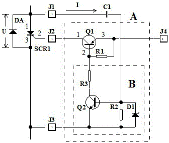
[0053] One of the embodiments of the semi-controlled device driving device of the present invention, such as figure 2 Shown:

[0054] A half-controlled device driving device, including a first capacitor C1 and a semiconductor switch (A), the voltage signal at both ends of the half-controlled device SCR1 (unidirectional thyristor) to be driven is transmitted to the semiconductor switch (A) through the first capacitor C1 ), the semiconductor switch (A) is connected in series in the driving circuit of the semi-controlled device SCR1. Note: The connection between the first capacitor C1 and the semiconductor switch (A) is a voltage detection switch.

[0055] Semiconductor switch (A): composed of semiconductor devices and resistors, including the first transistor Q1 (which is a triode, and equivalent devices such as field effect transistors can also be used), detection circuit (B), and the first resistor R1. The first transistor Q1 is PNP type tube, the input end of the detection...


PUM


Abstract

The invention discloses a driving method and device of a semi-control type device and a mixed device, belongs to the field of electricity, and particularly relates to a driving method which is applied to a tiny non-driving dead zone or a driving dead zone of a semi-control type device of a silicon controlled rectifier and the like, a semi-control type driving device applied to a tiny non-conduction dead zone and a conduction dead zone used in the driving loop of the semi-control device of the silicon controlled rectifier and the like, and a mixed type device of the tiny non-conduction dead zone or the conduction dead zone. According to the driving method of the semi-control type device, a voltage detection switch is adopted, the input end of the voltage detection switch is connected to the two ends of the semi-control device to be driven, the voltage detection switch is connected to the driving loop of the semi-control type device in series, the potential difference of the voltage detection switch at the two ends of the semi-control type device is no larger than the conduction when the semi-control type device is at on-state voltage, and the voltage detection switch cuts off after detecting that the semi-control type device is conducted. The driving method and device of the semi-control type device and the mixed type device have the advantages that the non-driving dead zone or the driving dead zone is tiny.

Description

technical field [0001] The driving method and device for semi-controlled devices of the present invention belong to the field of electricity, in particular a driving method suitable for semi-controlled devices such as thyristors with no driving blind area or a very small driving blind area, and a driving method suitable for semi-controlled devices such as thyristors. A semi-controlled driving device with no driving dead zone or a very small driving dead zone used in the drive circuit of the device, and a hybrid device with no or very small conduction dead zone. Background technique [0002] At present, in electronic control systems that require frequent switching of loads, thyristors (semi-controlled devices) are widely used to switch resistive, inductive or capacitive loads. Related technologies for driving energy consumption, such as the patent number: ZL201110430747.7, and the patent name: triggering energy-saving devices and thyristor switches, the working principle disc...

Claims


Application Information

Patent Timeline
IPC IPC(8): H03K17/30H03K17/79
CPCH03K17/305H03K17/79H03K2217/0027
Inventor 郭桥石
Owner GUANGZHOU JINSHI ELECTRONICS
Why Eureka
Try Eureka