
A lock indicator based on frequency comparison

A technology of frequency comparison and locking indication, applied in automatic control of power, electrical components, etc., can solve the problems of high bit error rate and failure to cover all frequency bands, and achieve the effect of low bit error rate and wide coverage frequency range

Active Publication Date: 2019-12-24
SHANGHAI HUALI MICROELECTRONICS CORP
View PDF7 Cites 0 Cited by
  • Summary
  • Abstract
  • Description
  • Claims
  • Application Information

AI Technical Summary

Problems solved by technology

[0004] 1. The filter can only be designed for a specific frequency and cannot cover all frequency bands
[0005] 2. Through phase judgment and locking, the bit error rate is high
[0006] 3. Other circuits are needed to generate the VREF voltage

Method used


Image

  • A lock indicator based on frequency comparison
  • A lock indicator based on frequency comparison
  • A lock indicator based on frequency comparison

Examples


Embodiment Construction

[0033] The implementation of the present invention is described below through specific examples and in conjunction with the accompanying drawings, and those skilled in the art can easily understand other advantages and effects of the present invention from the content disclosed in this specification. The present invention can also be implemented or applied through other different specific examples, and various modifications and changes can be made to the details in this specification based on different viewpoints and applications without departing from the spirit of the present invention.

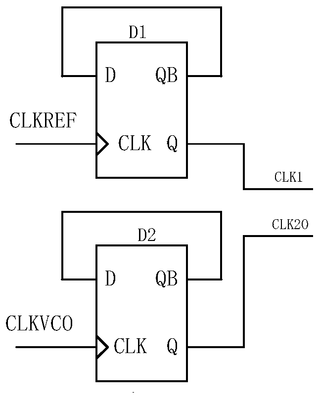
[0034] figure 2 It is a structural schematic diagram of a locking indicator based on frequency comparison in the present invention. Such as figure 2 As shown, a locking indicator based on frequency comparison in the present invention includes a waveform adjustment unit 10 , an edge discriminator 20 and a counter 30 .

[0035] The waveform adjustment unit 10 is composed of an even number...


PUM


Abstract

The invention discloses a lock indicator based on frequency comparison. The lock indicator comprises a waveform adjustment unit, an edge frequency detector and a lock indication generation unit, wherein the waveform adjustment unit is used for respectively shaping a reference clock and a VCO clock to a shaped reference clock and a shaped VCO clock of a duty ratio being 50%; the edge frequency detector is used for carrying out frequency comparison on the shaped reference clock and the shaped VCO clock and outputting frequency error pulse; the lock indication generation unit is used for counting the shaped reference clock under the control of the frequency error pulse and carrying out AND operation on an output count to obtain a lock indication signal. Through adoption of a pure digital circuit, functions of the lock indicator are realized, and the lock indicator has the advantages of wide coverage frequency range, low code rate and capability of accurately setting a frequency error range during locking.

Description

technical field [0001] The present invention relates to a lock indicator, in particular to a lock indicator based on frequency comparison. Background technique [0002] The locking indicator of the traditional phase comparison method such as figure 1 As shown, the two clocks CLK1 and CLK2O pass through the phase frequency detector (PFD), output U and D signals, and then pass through an OR gate. At this time, the duty cycle of the output (Y) of the OR gate represents the phase difference between CLK1 and CLK2O . This signal is compared with the reference voltage VREF after passing through a low-pass filter. If the phase difference between CLK1 and CLK2O is relatively large, the duty cycle of Y will be relatively large, and the output voltage (VIN) will be relatively high after passing through the filter. If VIN>VREF, then the lock indicator output is low; if CLK1 and CLK2O phase Close, VIN<VREF, then the lock indicator output is high. Selecting the appropriate VREF acc...

Claims


Application Information

Patent Timeline
Patent Type & Authority Patents(China)
IPC IPC(8): H03L7/197
CPCH03L7/197
Inventor 张宁陈璐王志利顾文涛
Owner SHANGHAI HUALI MICROELECTRONICS CORP
Learn More