Spaceborne high-speed LVDS parallel signal quick test and analysis method

A signal test and signal technology, applied in transmission monitoring, digital transmission systems, electrical components, etc., can solve the problems of inability to locate and analyze bit errors, high test costs, and unintuitive characteristic analysis, etc., to solve the problems of inability to quickly test and accurately Analysis, simplification of the test system, and the effect of reducing the test cost

Active Publication Date: 2017-05-31
SHANGHAI SATELLITE ENG INST
View PDF2 Cites 2 Cited by
  • Summary
  • Abstract
  • Description
  • Claims
  • Application Information

AI Technical Summary

Problems solved by technology

The bit error rate test needs to build a complete set of data sending and receiving and comparison active system, which can adapt to the requirements of different transmission frequencies and transmission bit widths, and accumulate enough test samples according to the bit error rate requirements, not only the cost of testing equipment and testing process High, and it is impossible to effectively locate and analyze the occurrence of bit errors
TTL signal test needs to design a set of signal level conversion active equipment that matches the signal sending and receiving, which belongs to the signal internal conversion interface test and cannot directly reflect the characteristics of the LVDS signal as the external interface of the product.
[0005] If an LVDS parallel interface is required to adapt to different rates and bit widths and meet the requirements of normal data transmission, it is necessary to conduct comprehensive tests and characteristic analysis on various rates and bit width states. This is impossible to achieve with the original test method, and a new A fast test and analysis method for LVDS parallel signals
[0006] Therefore, the prior art LVDS parallel signal test method mainly has the technical problems of high test cost and unintuitive characteristic analysis

Method used


Image

  • Spaceborne high-speed LVDS parallel signal quick test and analysis method
  • Spaceborne high-speed LVDS parallel signal quick test and analysis method
  • Spaceborne high-speed LVDS parallel signal quick test and analysis method

Examples


Embodiment 1

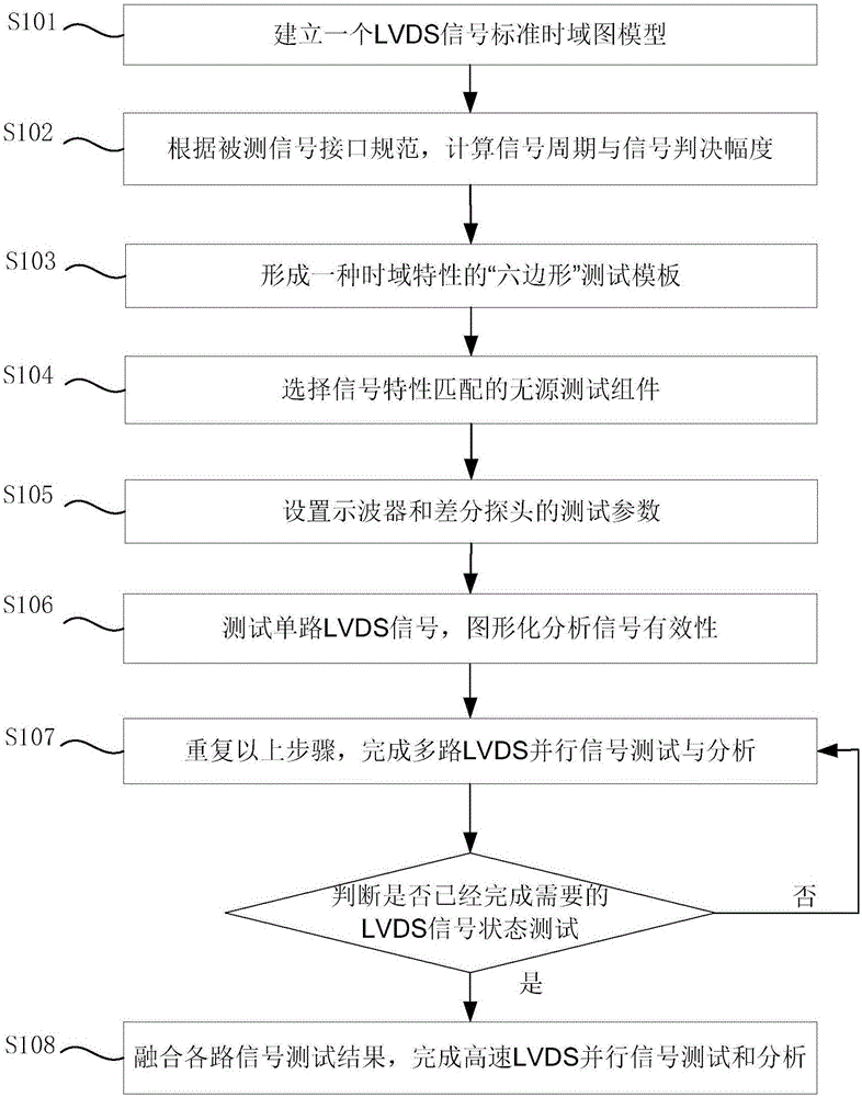
[0053] Please refer to Figure 3-Figure 7 , to illustrate the specific mode of the present invention.

[0054] The present invention will be described in further detail below in conjunction with the accompanying drawings and specific embodiments:

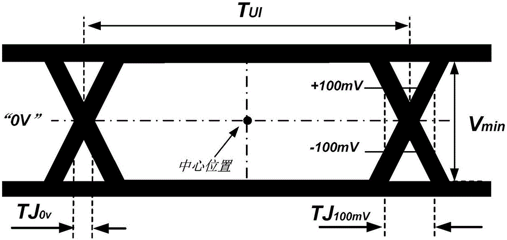
[0055] based on T UI , V min , TJ 0V , TJ 100mV Four parameters are used to establish a standard time-domain graph model of LVDS signal. Under ideal rectangular wave conditions, both zero jitter and reference jitter are zero. TJ is required in this example 0V ≤10%T UI , TJ 100mV ≤20%T UI ,See image 3 .

[0056] According to the transmission requirements of the tested LVDS parallel signal, calculate the signal period and threshold amplitude, and determine the time domain graph model that conforms to the characteristics of the interface signal. The parameters in this example are: T UI =8ns, V min= 300mV, then TJ 0V ≤0.8ns, TJ 100mV ≤1.6ns, see Figure 4 .

[0057] T based on time-domain graphical model a , T b , V ...


PUM


Abstract

The invention provides a spaceborne high-speed LVDS parallel signal quick test and analysis method. The method comprises the following steps: 1, an LVDS signal standard time domain graph model is built; 2, according to an interface specification of tested signals, a signal cycle and a signal judgment amplitude are calculated; 3, a hexagon test template with a time domain feature is formed; 5, a passive test module with matched signal features is selected; 5, test parameters for an oscilloscope and a differential probe are set; 6, single-channel LVDS signals are tested, and signal effectiveness is analyzed graphically; 7, the above steps are repeated to complete multichannel LVDS parallel signal test and analysis; and 8, test results of multiple channels of signals are fused, and high-speed LVDS parallel interface test and analysis are completed. The method is applicable to a parallel LVDS interface at each transmission rate, and technical problems that the LVDS parallel interface can not be quickly tested and accurately analyzed can be solved.

Description

technical field [0001] The invention relates to a method for fast testing and analysis of signals, in particular to a method for fast testing and analysis of on-board high-speed LVDS parallel signals. Background technique [0002] LVDS (Low Voltage Differential Signal) parallel signal is an important data transmission signal for spacecraft. Due to its low transmission voltage, strong anti-interference ability, high transmission rate, and high interface stability, it plays an important role in the field of spacecraft data transmission. important role. In data transmission applications, the LVDS parallel signal interface is required to transmit accurately and work stably, not affected by external environmental factors, nor between internal multi-channel parallel signals, and requires a comprehensive test of the interface signal function and performance and analyse. [0003] The data transmission rate of on-board LVDS parallel signals has developed from a few Mbps to hundreds...

Claims


Application Information

Patent Timeline
Patent Type & Authority Applications(China)
IPC IPC(8): H04B17/00H04B17/10H04B17/20H04B17/23H04L12/26
CPCH04B17/00H04B17/0085H04L43/08H04L43/0823H04B17/101H04B17/20H04B17/23
Inventor 朱少杰张小锋李科姜岩
Owner SHANGHAI SATELLITE ENG INST
Why Eureka
Try Eureka