
A compensating driving device and its realization method

A technology of a driving device and an implementation method, which is applied in the direction of lighting devices, light sources, electrical components, etc., can solve the problem that the temperature coefficient compensation accuracy cannot fully meet the performance requirements of LED drivers, etc., and achieves the improvement of load adjustment rate and temperature coefficient and low cost. , Improve the effect of load regulation

Active Publication Date: 2018-10-09
HENGDIAN GRP TOSPO LIGHTING
View PDF5 Cites 0 Cited by
  • Summary
  • Abstract
  • Description
  • Claims
  • Application Information

AI Technical Summary

Problems solved by technology

However, due to cost reasons, the load regulation rate and temperature coefficient compensation accuracy of many control chips cannot fully meet the performance requirements of LED drivers.
This presents new challenges for driver design

Method used


Image

  • A compensating driving device and its realization method
  • A compensating driving device and its realization method

Examples


Embodiment 1

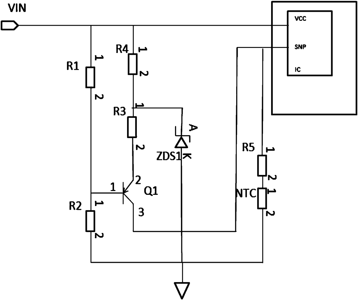
[0031] Such as Figure 1~2 As shown, a compensating drive device includes a VCC circuit that converts an input AC signal into a DC signal and simultaneously starts and controls the device; a compensation circuit that adjusts load regulation and temperature coefficient; a power converter including a chip control module ; Wherein, the power converter is connected to the VCC circuit and the compensation circuit respectively.

[0032] The compensation circuit in this embodiment includes an amplification circuit and a shunt circuit. Such as figure 2 As shown, the amplifying circuit includes a first resistor R1, a second resistor R2, a third resistor R3, a fourth resistor R4, a first voltage regulator transistor ZDS1 and a first triode Q1; wherein, the first end of the first resistor R1 and The second circuit is connected, the second end of the first resistor R1 is connected with the first end of the second resistor R2 and the base of the first triode Q1, the second end of the se...


PUM


Abstract

The invention discloses a compensating driving device, which comprises a VCC circuit which converts an input AC signal into a DC signal and simultaneously starts and controls the device; has a compensation circuit for adjusting the load adjustment rate and temperature coefficient; and includes a chip control module for power conversion device; wherein, the power converter is connected to the VCC circuit and the compensation circuit respectively. The invention also discloses a method for realizing the compensation driving device. The invention has the characteristics of simple structure, low cost, greatly improved load adjustment rate and temperature coefficient, and the like.

Description

technical field [0001] The invention relates to LED control circuit technology, in particular to a compensation driving device and a realization method thereof. Background technique [0002] With the continuous development of society, the lighting industry is changing with each passing day. As a replacement of incandescent lamps, energy-saving lamps and other non-energy-saving light sources, LED lighting products are favored by more and more consumers due to their long life, no pollution, and the advantages of green environmental protection and energy-saving lamps. . For lighting products, in addition to their own lighting functions, people also have higher and higher requirements for their electrical performance and service life in various environments. requirements become more stringent. [0003] Facing the increasingly competitive LED lighting market, the cost of LED lighting products continues to decrease, the functions continue to increase, and the stability of produc...

Claims


Application Information

Patent Timeline
Patent Type & Authority Patents(China)
IPC IPC(8): H05B33/08H05B44/00
CPCH05B45/37
Inventor 孔剑虹程琳琳赵志峰杜毅彪徐健
Owner HENGDIAN GRP TOSPO LIGHTING
Learn More