

Sealing device
A technology of sealing device and sealing fluid, which is applied in the direction of engine sealing, bearings, shafts, etc., can solve the problems of increasing the number of parts, increasing the size of the radial direction, and not being able to apply mechanical seals as they are, so as to improve the sealing performance , The effect of preventing the increase of slip torque and suppressing the increase of viscosity
- Summary
- Abstract
- Description
- Claims
- Application Information
AI Technical Summary
Problems solved by technology
Method used
Image

Examples
Embodiment 1
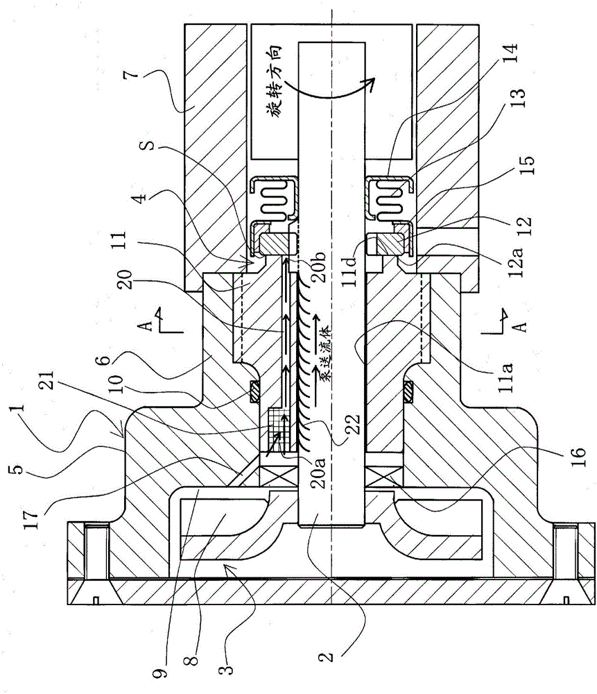
[0041] refer to figure 1 , the sealing device according to Embodiment 1 of the present invention will be described.
[0042] figure 1 The first embodiment shown shows a case where the sealing device of the present invention is applied to a small pump, and the sealing device is arranged adjacent to a pump chamber for pressure-feeding liquid.
[0043] The sealing unit of this sealing device is an exterior that seals the fluid to be sealed on the side of the high-pressure fluid that leaks from the inner periphery of the sealing surface (in the present invention, it may also be referred to as "sliding surface") toward the outer periphery. form of mechanical seals.
[0044] exist figure 1 In the figure 1 The pump part 3 is formed on the left side in the middle), and the pump part 3 is formed on the other end side (in the figure 1 The right side in the center) is formed with a mechanical seal 4 as a sealing unit.
[0045] In addition, the housing 1 mainly includes a pump ...
Embodiment 2
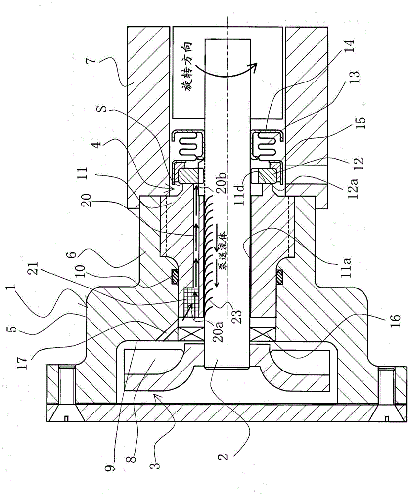
[0085] refer to image 3 A sealing device according to Example 2 of the present invention will be described.
[0086] The sealing device involved in embodiment 2 and figure 1 as well as figure 2 The difference of Embodiment 1 shown is that the pumping groove on the outer peripheral surface of the rotating shaft is configured to transfer the sealed fluid from the sliding surface S side to the pump chamber side (the sealed fluid source side). Example 1 is basically the same, for figure 1 as well as figure 2 The same components are marked with the same symbols, and repeated descriptions are omitted.
[0087] exist image 3 Among them, a pumping groove 23 for transferring the sealed fluid from the sliding surface S side to the pump chamber 9 (the sealed fluid source side) is provided on the outer peripheral surface of the rotating shaft 2 . The pumping groove 23 is not particularly limited as long as it can transfer the fluid to be sealed from the side of the sliding sur...
Embodiment 3
[0100] refer to Figure 4 A sealing device according to Example 3 of the present invention will be described.
[0101] The sealing device involved in embodiment 3 and figure 1 The difference between Embodiment 1 and 2 is that a lip seal is used as a sealing unit instead of a mechanical seal, but other points are basically the same as Embodiment 1. figure 1 And 2, the same components are marked with the same symbols, and repeated explanations are omitted.
[0102] exist Figure 4 in, not as figure 1 As in the case of Embodiment 1 shown in 2 and 2, the fixed-side seal ring 11 is also used as a radial sliding bearing, and dedicated seal units and bearings are respectively provided.
[0103] The lip seal 30 as a sealing unit is installed in the seal cover 7 and is slidably in close contact with the peripheral surface of the rotating shaft 2, and has a first sealing lip member 31 made of rubber material disposed on the pump unit 3 side and disposed on the pump portion 3 side. ...
PUM
 Abstract
Description
Claims
Application Information