Supercharge Your Innovation With Domain-Expert AI Agents!

Heat exchange ventilation device

A ventilation device and heat exchanger technology, applied in heating methods, household heating, heat recovery systems, etc., can solve problems such as condensation and cold air flow, and achieve the effect of preventing excessive temperature rise and suppressing frequent on and off

Active Publication Date: 2019-06-14
MITSUBISHI ELECTRIC CORP
View PDF8 Cites 0 Cited by
  • Summary
  • Abstract
  • Description
  • Claims
  • Application Information

AI Technical Summary

Problems solved by technology

[0002] In cold regions, when the outside air is introduced into the room without change, the following problems may occur: condensation or cold air flow that gives a feeling of cold wind.

Method used


Image

  • Heat exchange ventilation device
  • Heat exchange ventilation device
  • Heat exchange ventilation device

Examples


Embodiment approach 1

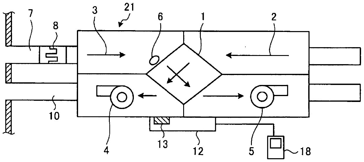
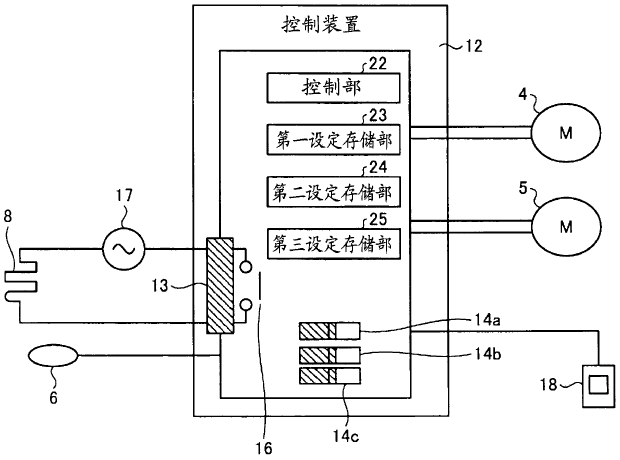
[0028] figure 1 It is a figure which shows the structure of the heat exchange ventilator which concerns on Embodiment 1 of this invention. The heat exchange ventilation device 21 has: an air supply duct 3, which is used to guide the outside air to the room; an exhaust duct 2, which is used to guide the indoor air The air is guided to the outside; the air supply blower 5 is arranged on the air supply duct 3 and generates air supply from outside to the room; the exhaust blower 4 is arranged on the exhaust air Road 2, and generate exhaust flow from indoor to outdoor; heat exchanger 1, said heat exchanger 1 is arranged in the middle of air supply air duct 3 and exhaust air duct 2, and passes through air supply air duct 3 heat exchange between the supply air flow and the exhaust flow passing through the exhaust air duct 2 ; and the control device 12 , which controls the operation of the supply air blower 5 and the exhaust blower 4 . A remote controller 18 for operating the heat e...

Embodiment approach 2

[0051] Figure 4 It is a figure which shows the structure of the heat exchange ventilator of Embodiment 2 of this invention. The heat exchange ventilator 26 of Embodiment 2 is not provided with the heater connection terminal 13, and instead of the externally connected heater 8, the built-in heater 27 is provided in the air supply duct 3, which is different from that of figure 1 The heat exchange ventilator 21 of Embodiment 1 shown is different. The built-in heater 27 is a heater that heats the supply air flowing into the heat exchanger 1 through the supply air duct 3 .

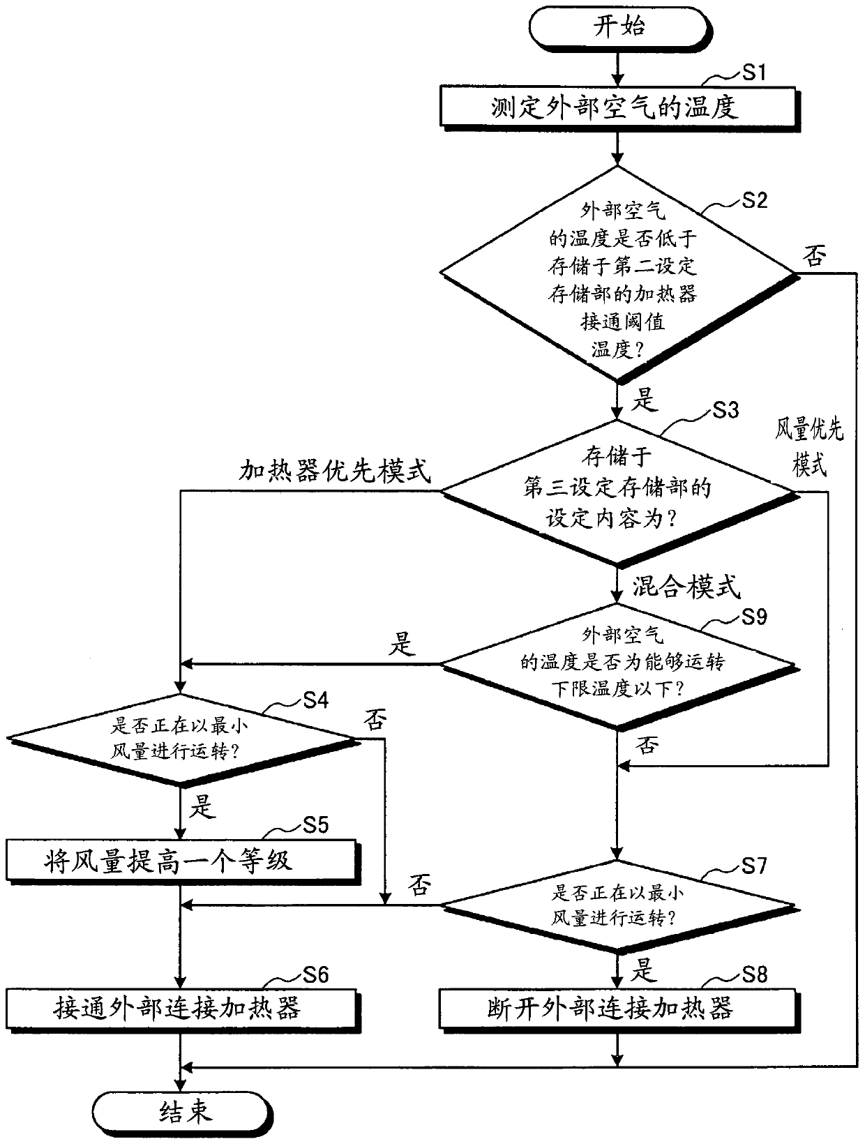
[0052] In the heat exchange ventilator 26 according to Embodiment 2, information indicating whether or not to use the heater is stored in the first setting storage unit instead of information indicating whether or not the heater is connected. The action of heat exchange ventilator 26 and image 3 The operation of the heat exchange ventilator 21 according to Embodiment 1 shown is the same.

[0053] The heat...


PUM


Abstract

A heat exchange and ventilation device, comprising: a heater connection terminal, which is connected with an external connection heater (8), and the external connection heater is arranged in an outside air supply pipeline connected to the outside of the air supply air duct, And heat the supply air flowing into the heat exchanger through the air supply duct; the temperature sensor (6) measures the temperature of the supply air passing through the air supply duct; the control part (22), based on the temperature sensor The measurement results of (6) control the operation of the supply air blower (5) and the exhaust blower (4) and the on-off of the externally connected heater (8), and the supply air blower (5) can generate The air supply air flow is operated at multiple intensities with different air volumes, and the control unit (22) prohibits obtaining the information that the air supply blower (5) is operated at a lower intensity than the preset intensity and the externally connected heater (8) is turned on. state.

Description

technical field [0001] The present invention relates to a heat exchange ventilator having a heater for heating outside air introduced into a heat exchanger from the outside. Background technique [0002] In a cold region, when the outside air is introduced into the room without change, there may be a problem that condensation is generated or a cold airflow that gives a feeling of cool wind is generated. Therefore, when the temperature of the outside air is lower than the heater ON threshold temperature, the outside air may be supplied into the room after being heated by the heater. [0003] If it is a product with a built-in heater that can adjust temperature by control or a PTC (positive temperature coefficient: positive temperature coefficient) heater, it can continue heating and ventilation by heater. For the heater, in order to simplify the control and to suppress the cost and size, a method of controlling the heater only by turning on and off the power to the heater is...

Claims


Application Information

Patent Timeline
Patent Type & Authority Patents(China)
IPC IPC(8): F24F7/08F24F7/007
CPCF24F2221/34F24F11/77F24F11/30F24F12/006Y02B30/56Y02B30/70F24F2110/10F24F11/76F24F11/56F24F11/65F24F7/08F25B49/02F25B2313/0294F25B2600/111
Inventor 长谷川耕平松本耕平芦野正史斋藤文夫
Owner MITSUBISHI ELECTRIC CORP
Features
  • R&D
  • Intellectual Property
  • Life Sciences
  • Materials
  • Tech Scout
  • Unparalleled Data Quality
  • Higher Quality Content
  • 60% Fewer Hallucinations
Learn More