Steam-water separating box drainage system of sealing oil vacuum pump

A steam-water separation and drainage system technology, applied in the field of separator drainage system, can solve problems such as increased workload of operating personnel, potential safety hazards, damage to mechanical equipment, etc., to prevent lubricant oil overflow, reduce personnel monitoring, and improve drainage speed Effect

Pending Publication Date: 2017-06-06
DATANG HANCHENG NO 2 POWER GENERATION
View PDF6 Cites 0 Cited by
  • Summary
  • Abstract
  • Description
  • Claims
  • Application Information

AI Technical Summary

Problems solved by technology

[0003] At present, due to the momentary positive pressure in the steam-water separation box of the separator when the vacuum pump is started, the lubricating oil is sprayed out through the overflow pipe, polluting the ground and surrounding equipment, and posing safety hazards
After the vacuum pump starts normally, the oil level in the steam-water separation box is insufficient due to part of the oil and/or water being sprayed out. At the same time, since the oil in the separation box is used for vacuum pump lubrication and oil replacement, the lubricating oil will also be lost during the normal operation of the vacuum pump. , so it is necessary to replenish the oil in the steam-water separation tank. Every time the vacuum pump is started, it needs to be monitored and replenished on the spot, which increases the workload of th

Method used


Image

  • Steam-water separating box drainage system of sealing oil vacuum pump
  • Steam-water separating box drainage system of sealing oil vacuum pump

Examples


Example Embodiment

[0048] Example one

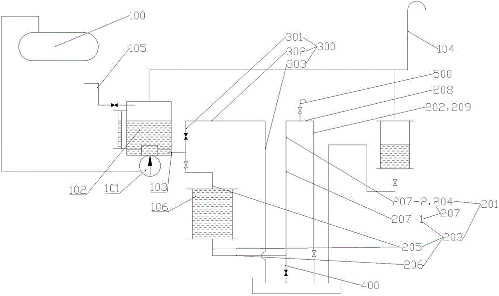
[0049] Such as figure 1 As shown, the generator sealing oil system includes a sealing oil vacuum tank 100, a vacuum pump for exhausting moisture in the sealing oil vacuum tank 100, and a steam-water separation tank 102 drainage system of the vacuum pump. The vacuum pump includes a vacuum pump body 101 and a steam-water separation tank 102. , The drainage system of the steam-water separation tank 102 of the vacuum pump includes an overflow pipe connected with the steam-water separation tank 102. The air inlet of the vacuum pump body 101 communicates with the sealed oil vacuum box 100, the moisture in the sealed oil vacuum box 100 is pumped out by the vacuum pump, and the exhaust port of the vacuum pump body 101 is connected with the steam-water separation box 102, and the extracted gas is discharged into the soda Separating box 102.

[0050] An exhaust pipe 104 is provided on the top of the steam-water separation box 102, and an oil supplement pipe 105 is provi...

Example Embodiment

[0072] Example two

[0073] Such as figure 1 As shown, on the basis of the first embodiment, the drainage system of the steam-water separation tank 102 of this embodiment further includes an oil drain pipe 400 for quickly draining the liquid in the buffer device 106, the oil drain pipe 400 and the buffer device 106 is connected to or connected to an overflow pipe located at the lower part of the buffer device 106.

[0074] When the discharge speed of the liquid in the steam-water separation tank 102 is too fast, the buffer device 106 is filled or even sprayed at the liquid outlet of the overflow pipe, the liquid in the buffer device 106 can be quickly discharged by opening the oil drain pipe 400 , Quickly reduce the liquid pressure in the overflow pipeline, stop spraying, and improve the safety of the overflow pipeline. At the same time, when the sealing oil system fails or is overhauled, by opening the oil drain pipeline 400, the steam and water separation tank 102 and All the li...

Example Embodiment

[0080] Example three

[0081] Such as figure 1 As shown, on the basis of the first and second embodiments, the drainage system of the steam-water separation tank 102 of this embodiment further includes an overflow pipe 300 for quickly reducing the height of the liquid level in the steam-water separation tank 102. The overflow The inlet end of the pipe 300 communicates with an overflow pipe between the buffer device 106 and the steam-water separation tank 102.

[0082] The inlet end of the overflow pipe 300 can also communicate with the steam-water separation tank 102.

[0083] By setting the overflow pipe 300, when the liquid in the steam-water separation tank 102 increases too much or too fast, the overflow pipe 300 assists the overflow pipe to reduce the liquid level in the steam-water separation tank 102, so that the liquid level is lowered as soon as possible to prevent overflow The liquid in the pipeline splashes, polluting the surrounding space and causing danger.

[0084] Furt...


PUM


Abstract

The invention belongs to the field of separator drainage systems, and specifically relates to a steam-water separating box drainage system of a sealing oil vacuum pump. The steam-water separating box drainage system comprises an overflow pipeline communicated with a steam-water separating box, wherein the overflow pipeline is provided with a buffer device for buffering the pressure in the steam-water separating box; the buffer device is communicated with the overflow pipeline; and when the sealing oil vacuum pump is started, the steam-water separating box has an instant positive pressure, lubricating oil or oil and water are sprayed out through the overflow pipeline to pollute the ground and peripheral equipment, and potential safety hazards exist. Because the oil and water are sprayed out after the vacuum pump is started normally or because of an insufficient oil level in the steam-water separating box due to the loss of lubricating oil and the like, the steam-water separating box needs to be supplemented with oil, the operation requires on-site monitoring and oil supplementation, and the workload of operating personnel is increased. By setting the buffer device to absorb the instant positive pressure, the overflow of the lubricating oil is reduced or even eliminated, the potential safety hazards are reduced, the oil level is stabilized, the number of oil supplementation and personnel monitoring is reduced, and the steam-water separating box drainage system is safer, more time-saving and more labor-saving.

Description

technical field [0001] The invention belongs to the field of separator drainage systems, in particular to a drainage system for a steam-water separation box of a sealed oil vacuum pump. Background technique [0002] The generator sealing oil system is an important equipment system of the power plant, which is used to seal the hydrogen of the generator so that it is tight and does not leak. The sealed oil vacuum pump needs to extract the insoluble gas and water vapor inside the sealed oil tank to achieve the purpose of establishing a vacuum inside the sealed oil tank and removing water in the oil. The moisture-containing gas extracted by the vacuum pump is discharged into the separator, and the moisture-containing gas is separated from the gas-water in the separator due to the pressure reduction. The separator has an oil supply port to ensure the operation of the vacuum pump, and the gas-water separation to the separator through the oil supply port The lubricating oil added ...

Claims


Application Information

Patent Timeline
IPC IPC(8): B01D49/00
CPCB01D49/003
Inventor 孔德斌王巍强智文徐谦益孙文全张学利赵东林张建峰田宏志王刚
Owner DATANG HANCHENG NO 2 POWER GENERATION
Why Eureka
Try Eureka