A cell 3D printer

A 3D printer and cell technology, applied in the field of 3D printers that can print cells, can solve the problems of easy dislocation, inaccurate, clear, and difficult to locate the outline of the stent, and achieve the effect of improving the shape and size accuracy.

Inactive Publication Date: 2017-06-06
SHANGHAI FOCHIF ELECTROMECHANICAL TECH
View PDF3 Cites 7 Cited by
  • Summary
  • Abstract
  • Description
  • Claims
  • Application Information

AI Technical Summary

Benefits of technology

This patented technology allows two different solutions (gel material or liquid) from separate sources are injected into one another through an extrusion gun that forms tiny fibers called catheters inside each fluid stream before being deposited onto the surface where they will be used to create 3D structures made up of these materials. These techniques allow for precise control over how well the resulting structure looks like it should look good when placed back down after manufacturing processes.

Problems solved by technology

This patented technical describes how current techniques used to create tissue engineered materials have drawbacks including difficulties controlling their microstructures due to blockages caused by pores or other gaps within them. Additionally, they require complicated processes like mixing collagen solutions together before adding cells to the material. These issues make these techniques challenging when trying to achieve high precision and accuracy in producing specific types of tissue constructs needed for medical applications.

Method used


Image

  • A cell 3D printer
  • A cell 3D printer

Examples


Embodiment Construction

[0029] The above-mentioned features and advantages of the present invention can be better understood after reading the detailed description of the embodiments of the present disclosure in conjunction with the following drawings. In the drawings, components are not necessarily drawn to scale, and components with similar related properties or characteristics may have the same or similar reference numerals.

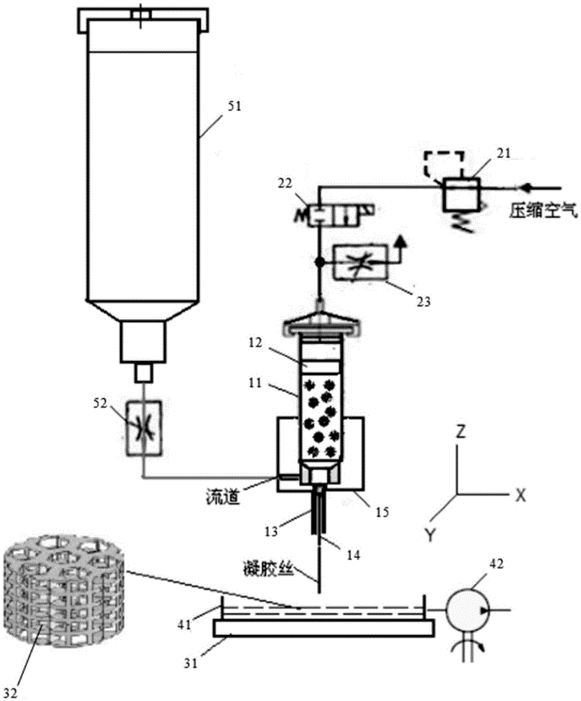
[0030] figure 2 The structure of an embodiment of the cell 3D printer of the present invention is shown. See figure 2 , The printer of this embodiment is composed of a nozzle, a feeding system, a pneumatic control system, a workbench, a liquid drainage system and a drive system.

[0031] The spray head includes: a syringe 11 , a piston 12 , a needle tube 13 , a needle 14 and a jacket 15 . The upper inlet of the syringe 11 is connected to the pneumatic control system through a hose, the lower end is matched with the needle tube 13 and the needle 14, and the inner cavity ...


PUM


Abstract

A cell 3D printer is disclosed. A shaped cell-containing stent is accurate and clear in shape, and free of stagger among layers. The cell 3D printer is suitable for printing tissue/organs having high shape requirements. According to a technical scheme, the cell 3D printer includes a spray head mixing and spraying a cell-containing gel precursor solution and a calcium ion solution, a material supplying system supplying the spray head with the calcium ion solution, a pneumatic control system controlling spraying action of the spray head, a workbench supporting the cell-containing stent printed and shaped, a liquid discharging system for discharging a liquid accumulated in a tray of the workbench, and a driving system for allowing the spray head to move at the X, Y and Z directions relative to the workbench.

Description


Claims


Application Information

Patent Timeline
Owner SHANGHAI FOCHIF ELECTROMECHANICAL TECH
Why Eureka
Try Eureka