Pressure relief wells and buildings

A technology for pressure relief wells and buildings, applied in buildings, industrial buildings, artificial islands, etc., to achieve the effects of avoiding damage, structural integrity, and efficient temperature control

Active Publication Date: 2020-05-22
SHENZHEN GENERAL INST OF ARCHITECTURAL DESIGN & RES
View PDF8 Cites 0 Cited by
  • Summary
  • Abstract
  • Description
  • Claims
  • Application Information

AI Technical Summary

Problems solved by technology

[0004] The purpose of the present invention is to provide a pressure relief well and its building to solve a series of problems in the prior art caused by directly setting the pressure relief port on the outer wall of the building in the protection zone

Method used


Image

  • Pressure relief wells and buildings
  • Pressure relief wells and buildings
  • Pressure relief wells and buildings

Examples


Embodiment 1

[0055] The present invention provides a pressure relief well, comprising a pressure relief well main body for forming a cavity of the pressure relief well, the main body of the pressure relief well includes an indoor part arranged inside a building, and protrudes from the indoor part to the building roof The outdoor part, the indoor part is provided with one or more pressure relief ports connected to the cavity of the pressure relief well and the indoor space of the building, and the outdoor part is provided with The exhaust port of the space; a normally closed smoke fire damper is installed on the pressure relief port.

Embodiment 2

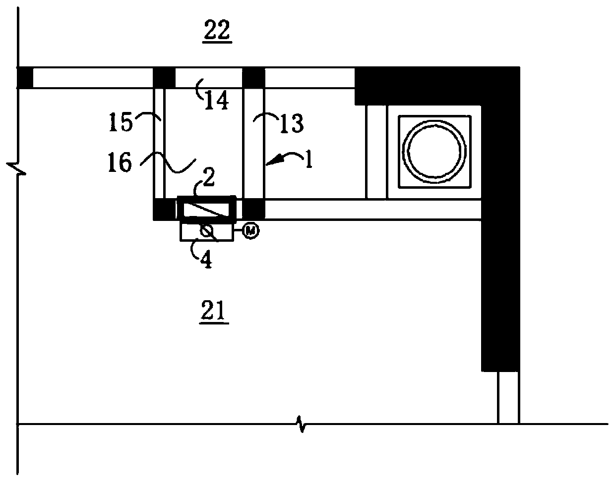
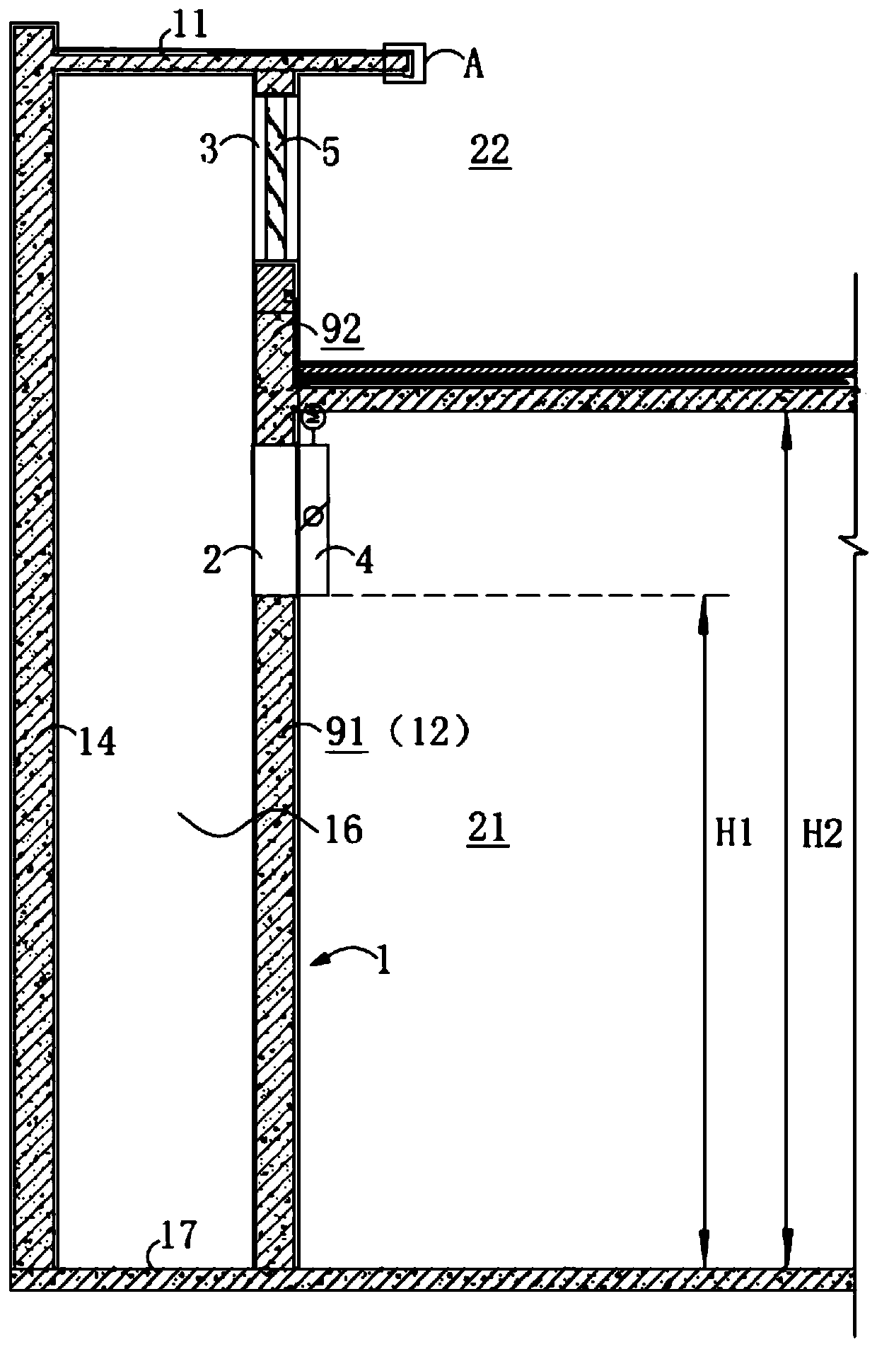
[0057] This embodiment provides a pressure relief well, which is used to relieve the pressure of the building when the building adopts a gas automatic fire extinguishing system for fire extinguishing. combine figure 1 , figure 2 As shown, the pressure relief well includes a pressure relief well body 1 for forming a pressure relief well cavity 16, a pressure relief port 2 and an exhaust port 3 respectively provided on the pressure relief well body 1, and a pressure relief port 2 installed on the pressure relief well body 1. The 280°C normally closed electric smoke exhaust fire damper 4 on the top and the aluminum alloy rainproof louver 5 installed on the exhaust port 3.

[0058] Wherein, the pressure relief well body 1 includes an indoor part 91 arranged inside the building and an outdoor part 92 protruding from the indoor part 91 to the roof of the building. The pressure relief port 2 is set in the indoor part 91 of the pressure relief well body for communicating the pressu...

Embodiment 3

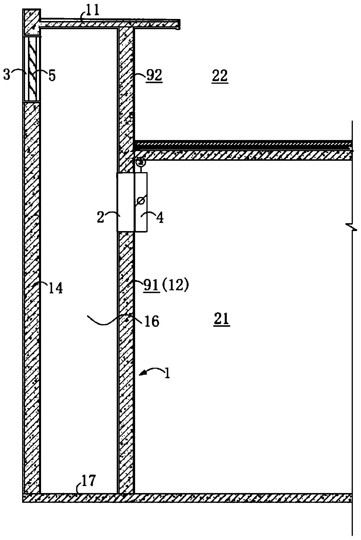
[0076] A five-storey building is provided with a pressure relief well, and the fourth and fifth floors of the building share the pressure relief well. It can be understood that, in the present invention, according to the actual floors of the building and the actual fire protection requirements, a shared pressure relief well can be set for floors with different numbers of floors. For example, when a building has ten floors, and the eighth floor to the tenth floor all have gas fire extinguishing and pressure relief requirements, the eighth floor to the tenth floor can be set to share the same pressure relief well. When the building has 20 floors, and the 15th to 20th floors, and the 8th to 9th floors all have gas fire extinguishing and pressure relief requirements, the same pressure relief well can be used on the corresponding floors above.

[0077] The only difference between the pressure relief well in this embodiment and the pressure relief well in Embodiment 2 is that, as ...


PUM


Abstract

The invention relates to the technical field of fire extinguishment for buildings, in particular to a pressure relief well. The pressure relief well comprises a main pressure relief well body for forming a pressure relief well cavity; the main pressure relief well body comprises an indoor part arranged in the building indoor space and an outdoor part bulging out of the roof of the building from the indoor part; the indoor part comprises one or more pressure relief ports communicating with the pressure relief well cavity and the building indoor space; the outdoor part comprises an exhaust port communicating with the pressure relief well cavity and the building outdoor space; and a normally-closed smoke discharging fire damper is mounted on each pressure relief port. With the pressure relief well, the outer wall structure of the building can be complete and reliable while gas fire-extinguishment and pressure relief in a protection zone is realized, and the appearance is better. Besides, with the pressure relief well, the indoor temperature control effect by the aid of an air conditioner cannot be affected, temperature control by the aid of the air conditioner is more energy-saving and efficient, the cleanliness of the indoor environment is guaranteed, and the service life of indoor equipment or products can be prolonged.

Description

technical field [0001] The invention relates to the technical field of building gas fire extinguishing, in particular to a pressure relief well and a building. Background technique [0002] At present, in the construction of large-scale data computer rooms, the protection area of ​​the main computer room is usually protected by a gas fire extinguishing system, especially a heptafluoropropane gas fire extinguishing system. Considering that after the gas is released, the pressure in the protected area will increase instantaneously, and this instantaneous pressurization may destroy the building envelope in the protected area, so it is necessary to set up a pressure relief port for reducing the air pressure in the protected area to ensure The building enclosure structure in the protection area of ​​the gas fire extinguishing system is safe and reliable, and can successfully extinguish the fire quickly and in time. [0003] The existing pressure relief port is usually directly s...

Claims


Application Information

Patent Timeline
Patent Type & Authority Patents(China)
IPC IPC(8): E02D29/12E04H5/02
CPCE02D29/12E04H5/02
Inventor 资慧琴朱思进
Owner SHENZHEN GENERAL INST OF ARCHITECTURAL DESIGN & RES
Why Eureka
Try Eureka