Heat state direct reduction iron furnace external cooling device and method

A cooling device and external cooling technology, applied in the direction of furnaces, shaft furnaces, furnace components, etc., can solve the problems of increased space height of vertical furnaces, easy bursting of materials, and reduced iron metallization rate, so as to save engineering investment costs and improve cooling effect Uniform, simple and reasonable structure

Active Publication Date: 2017-06-06
ACRE COKING & REFRACTORY ENG CONSULTING CORP DALIAN MCC
View PDF6 Cites 4 Cited by
  • Summary
  • Abstract
  • Description
  • Claims
  • Application Information

AI Technical Summary

Problems solved by technology

[0003] At present, the direct reduction iron furnace cooling method mainly adopts direct water cooling or indirect water cooling. Although the direct water cooling has high cooling efficiency, the material is easy to burst, and the iron is oxidized by water to produce a large amount of iron tetroxide, which reduces the production capacity. The metallization rate of iron; indirect water cooling is mainly cooled by the following methods: a water-cooled film wall or a water-cooled sleeve is installed below the vertical furnace grate to indirectly cool the direct reduced iron mixture, but this cooling method has the following deficiencies: ( 1) The water-cooled membrane wall or the water-cooled casing occupies a certain space height, which increases the space height of the vertical furnace, thereby increasing the construction cost and difficulty; Water-cooled film walls or water-cooled casings are installed below, which means that many water-cooled film walls or water-cooled casings will be installed in the entire project, and the cooling device cannot be centralized
Based on the above two reasons, after the traditional water-cooled membrane wall or water-cooled sleeve device is enlarged, the cooling effect is not good because the distance between the material at the center and the cooling wall increases.
[0005] Therefore, the current cooling device cannot be centralized and large-scale, and cannot meet the requirements of the continuous expansion of direct reduced iron production scale

Method used


Image

  • Heat state direct reduction iron furnace external cooling device and method
  • Heat state direct reduction iron furnace external cooling device and method
  • Heat state direct reduction iron furnace external cooling device and method

Examples


Embodiment Construction

[0034] The specific embodiment of the present invention will be further described below in conjunction with accompanying drawing:

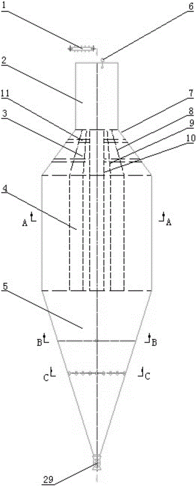
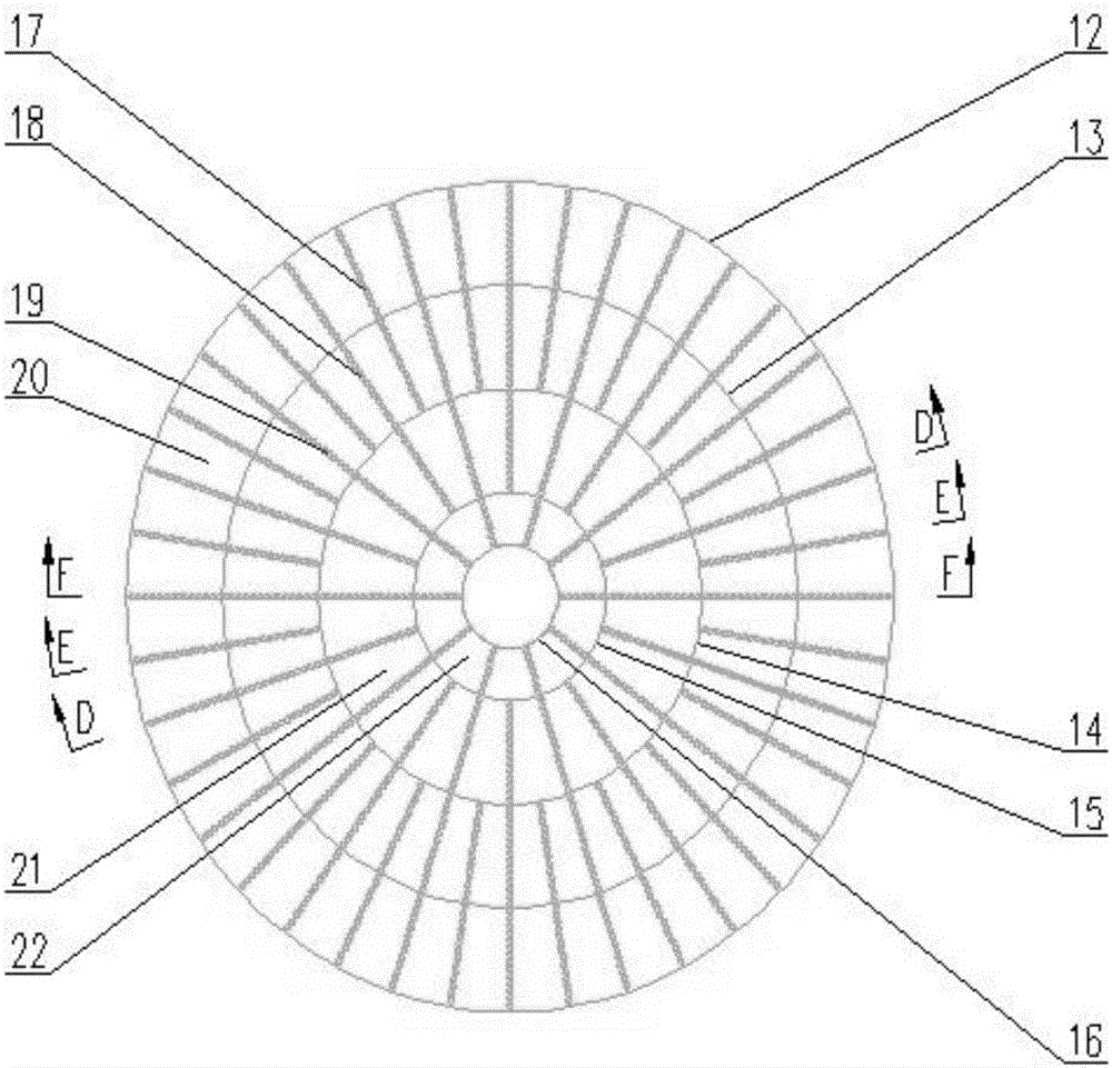
[0035] A thermal direct reduction iron furnace external cooling device according to the present invention includes a cooling device; the cooling device is composed of a buffer chamber 2, a distribution chamber 3, a cooling chamber 4 and a discharge chamber 5 arranged sequentially from top to bottom; the buffer The top of the chamber 2 is provided with a feed inlet; the distribution chamber 3 is coaxially provided with a cylindrical cylinder 10 and three conical cylinders 7-9 from the inside to the outside, wherein the top of the cylindrical cylinder 10 is closed, and the cylindrical The outer side of the cylinder 10 forms three bell mouth-shaped annular material passages that expand downward in sequence; the bottom of the cylindrical cylinder 10 and the conical cylinder 7-9 and the outer shell 12 of the cooling chamber 4 and three annular partition...


PUM


Abstract

The invention relates to a heat state direct reduction iron furnace external cooling device and method. The device is composed of a self caching chamber, a distribution chamber, a cooling chamber and a discharging chamber; the distribution chamber is internally provided with a cylindrical barrel and a taper barrel, and three annular material channels are sequentially formed on the outer side of the cylindrical barrel; the bottoms of the cylindrical barrel and the taper barrel are connected with a cooling chamber shell and the tops of three annular separating plates in a one-to-one correspondence manner, the cooling chamber is divided by the three annular separating plates into an inner layer annular cooling space, a center annular cooling space and an outer layer annular cooling space in the radial direction; and a plurality of cooling walls are evenly arranged in the cooling chamber in the circumferential direction, and the annular separating plates and the cooling walls divide the cooling chamber into a plurality of cooling boxes with vertical material falling channels in the radial direction and the circumferential direction correspondingly. Centralization and enlargement of the direct reduction iron mixture furnace external cooling device are achieved, it can be guaranteed that the cooling effect of reduction iron mixture discharged after cooling is even and coincident, and meanwhile the function of storing direct reduction iron is achieved.

Description

technical field [0001] The invention relates to the technical field of production of coal-based direct reduced iron, in particular to an external cooling device and method for hot direct reduced iron furnace. Background technique [0002] In the coal-based vertical furnace production of direct reduced iron, after cooling in the furnace, the temperature of the direct reduced iron mixture (direct reduced iron, residual carbon and ash) discharged from the vertical furnace is about 300-400 °C. Considering the high chemical activity of direct reduced iron, spontaneous combustion or even explosion and fire are very easy to occur at this temperature, so direct reduced iron must be cooled to a certain temperature before it can be transported and stored safely. [0003] At present, the direct reduction iron furnace cooling method mainly adopts direct water cooling or indirect water cooling. Although the direct water cooling has high cooling efficiency, the material is easy to burst, ...

Claims


Application Information

Patent Timeline
Patent Type & Authority Applications(China)
IPC IPC(8): F27D15/02C21B13/02
CPCF27D15/0286C21B13/02
Inventor 范程李振国杨俊峰袁朝晖杜光晨郑卫军
Owner ACRE COKING & REFRACTORY ENG CONSULTING CORP DALIAN MCC
Why Eureka
Try Eureka