Jet vacuum system for energy conservation transformation of thermal power plant and vacuum maintenance method

A technology for vacuum system and energy-saving transformation, which is applied in the direction of radial flow pumps, non-variable pumps, steam/steam condensers, etc. It can solve problems such as difficult to meet, vacuum pump pumping capacity decline, blade breakage, etc., and achieve significant economic efficiency. Benefits, reduced power consumption, and low water consumption

Pending Publication Date: 2017-06-06
WUHAN WU PUMP PUMP MFG
View PDF9 Cites 1 Cited by
  • Summary
  • Abstract
  • Description
  • Claims
  • Application Information

AI Technical Summary

Problems solved by technology

Taking the water ring vacuum pump as an example, in terms of safety: as the temperature of the working fluid in the pump body continues to rise, the pumping capacity of the vacuum pump drops sharply, and the vacuum cannot be maintained. Some even require two vacuum pumps to run at the same time, which is greatly affected by cavitation. Long-term operation will easily lead to blade breakage, threatening the safe operation of the unit
In terms of energy saving: when the unit is in normal operation, there is a large margin for maintaining the vacuum of the system. It will consume more energy to use the vacuum pump used to establish the vacuum in the condenser of the thermal power plant to maintain the vacuum. The transformation plan of the injection device has a certain energy saving rate (less than 20-30%), but at the expense of the design requirement of quickly establishing a vacuum, it is difficult to meet the design requirements of quickly establishing a start-up vacuum within 30 minutes
Generally speaking, cavitation and energy consumption are the main problems of vacuum pumps in domestic thermal power plants at present. Existing solutions cannot solve the safety and energy-saving problems of current water ring vacuum pumps at the same time, and may introduce unfavorable factors

Method used


Image

  • Jet vacuum system for energy conservation transformation of thermal power plant and vacuum maintenance method
  • Jet vacuum system for energy conservation transformation of thermal power plant and vacuum maintenance method

Examples


Embodiment Construction

[0026] In the following, the present invention will be described in detail and specifically through specific examples, so as to better understand the present invention, but the following examples do not limit the scope of the present invention.

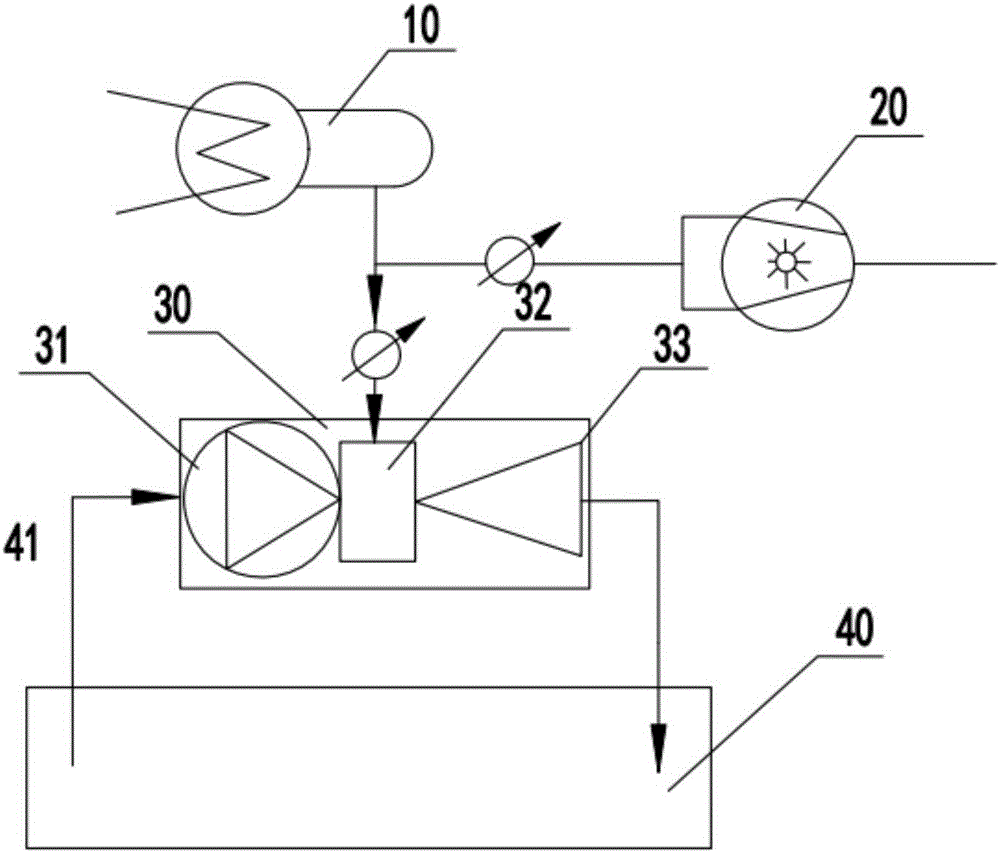
[0027] Such as figure 1 As shown, this embodiment proposes a centrifugal jet vacuum system for energy-saving transformation of thermal power plants, which is mainly aimed at areas with tight water resources. The centrifugal jet vacuum system is used for the energy-saving transformation of the condenser part of the vacuum system of the thermal power plant. The water inlet pipe and the water outlet pipe of the vacuum pump 30 are respectively connected with the pool 40, and the working water system is secondary circulating water. The centrifugal jet vacuum pump 30 is connected with the pool 40. The pool 40 is to ensure the working water of the centrifugal jet vacuum pump 30 on the one hand, and also has the function of dissipating the e...


PUM


Abstract

The invention discloses a centrifugal jet vacuum system for energy conservation transformation of a thermal power plant in a region which is short of water resource and a vacuum maintenance method of the centrifugal jet vacuum system. The system comprises a condenser (10), and a water ring vacuum pump (20) and a centrifugal jet vacuum pump (30) which are respectively communicated with an extraction opening of the condenser (10), wherein a water inlet pipe and a water outlet pipe of the centrifugal jet vacuum pump (30) are connected with a water tank (40) respectively; an operating water system adopts secondary circulating water. The centrifugal jet vacuum system realizes the establishment and maintenance of the vacuum system through a mode of taking the centrifugal jet vacuum pump as a main body which is matched with the water ring vacuum pump, solves double problems of cavitation and energy consumption caused by taking water as the operating medium of a vacuum pump in a national thermal power plant, has the advantages of low work dissipation, small noise and low water consumption, and has remarkable economic benefit and water saving characteristic.

Description

technical field [0001] The invention relates to a vacuum pumping system for a condenser of a power plant, in particular to a jet vacuum system and a vacuum maintenance method for energy-saving transformation of a thermal power plant, which are used to meet the requirements of energy-saving transformation of the cold end of the condenser of the thermal power plant. Background technique [0002] The condenser is an important part of the thermal power unit, and the performance of the condenser directly affects the thermal economy and safety of the entire unit. Due to the large size of the condenser and its auxiliary equipment, it is inevitable that air will leak into it. In order to prevent the accumulation of non-condensable gas in the condenser and increase its pressure, it is necessary to use a vacuum pump to extract the air in the condenser in time. And water vapor is the key to ensure the safe and economical operation of the entire unit. [0003] In a typical vacuum syste...

Claims


Application Information

Patent Timeline
Patent Type & Authority Applications(China)
IPC IPC(8): F28B9/10F04D17/10F04D17/18
CPCF04D17/10F04D17/18F28B9/10
Inventor 张怀明
Owner WUHAN WU PUMP PUMP MFG
Why Eureka
Try Eureka