Real-time as-fired coal burning caloricity monitoring system and monitoring method thereof

A technology of real-time monitoring and coal burning in the furnace, applied in the direction of power measurement, measuring device, torque measurement, etc., can solve the problems of lack of targeted treatment of boiler body differences, difficulty in adapting to industrial sites, lack of localized development, etc., to achieve The effects of avoiding boiler flameout accidents, reducing coal consumption for power supply, and safe operation

Inactive Publication Date: 2017-06-06
江苏铭彦科技有限公司
View PDF7 Cites 2 Cited by
  • Summary
  • Abstract
  • Description
  • Claims
  • Application Information

AI Technical Summary

Problems solved by technology

Recently, many domestic power generation plants have installed expensive but unreliable analytical instruments, such as flue gas emission composition instruments to monitor the composition of boilers after combustion. This has high requirements for on-site measurement and control instruments and does not meet China's actual national conditions.
At the same time, some common technologies are adopted, and there is a lack of targeted treatment of boiler body differences
In addition, foreign boiler combustion optimization control systems lack localized development, training and services are not in place, and it is difficult to adapt to the current situation of industrial sites in my country

Method used


Image

  • Real-time as-fired coal burning caloricity monitoring system and monitoring method thereof
  • Real-time as-fired coal burning caloricity monitoring system and monitoring method thereof
  • Real-time as-fired coal burning caloricity monitoring system and monitoring method thereof

Examples


Embodiment Construction

[0024] In order to make the technical solution of the present invention clearer, the present invention will be further described below in conjunction with the accompanying drawings.

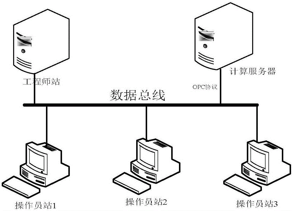
[0025] Such as figure 1 As shown, the present invention is a real-time monitoring system for the calorific value of coal fired into the furnace. The system uses modern engineering thermophysical algorithms and modern computer technology to establish real-time monitoring of boiler combustion. The system includes engineer stations and The operator station, the engineer station and the operator station are respectively connected to the calculation server of the DCS system of the generator set through the system bus, and it is characterized in that: the real-time monitoring system is connected with the DCS system of the generator set through the Ethernet, and from the generator set The real-time calculation data is obtained on the data bus of the DCS system, and the real-time calculation data is sent...


PUM


Abstract

The invention belongs to the technical field of monitoring of boiler burning processes of thermal power plants, and particularly relates to a real-time as-fired coal burning caloricity monitoring system and a monitoring method thereof. The system is used for establishing real-time boiler burning monitoring by adopting a modern engineering thermophysical algorithm and a modern computer technology, and comprises an engineer station and an operator station, which are connected with a system bus respectively, wherein the engineer station and the operator station are connected with a computing server of a DCS of a generating set through the system bus respectively, and the real-time monitoring system is connected with the DCS of the generating set, and is used for acquiring real-time computing data from a data bus of the DCS of the generating set and sending the real-time computing data to the data bus through an OPC protocol for the engineer station and the operator station to call. After the as-fired coal burning caloricity monitoring system is put into operation, operating personnel of a power plant can be guided to timely and accurately monitor the burning caloricity in a boiler and regulate burning of the boiler to ensure stable, efficient and safe operation of the generating set.

Description

technical field [0001] The invention belongs to the technical field of monitoring the combustion process of a boiler in a thermal power plant, and in particular relates to a real-time monitoring system and a monitoring method for the calorific value of coal fired into a furnace. Background technique [0002] At present, my country's electric power industry is gradually transitioning from a planned economic system to a market economic system. On the one hand, power generation companies face competition in the power market where power plants and grids are separated and bids are placed on the grid. production cost. Therefore, power generation enterprises urgently need to tap the potential of unit operation, improve unit operation efficiency, reduce production costs, and improve enterprise competitiveness. At present, for most thermal power plants in my country, due to the large variety of coal types and generally poor coal quality, in addition to the actual operation of the boi...

Claims


Application Information

Patent Timeline
IPC IPC(8): G01N25/44G01L3/26
CPCG01N25/44G01L3/26
Inventor 黄贤明
Owner 江苏铭彦科技有限公司
Why Eureka
Try Eureka