Monitoring camera with adjustable focal length

A monitoring camera and focal length technology, which is applied to cameras, exposure control, focusing devices, etc., can solve the problems of lack of data storage function, single video capture device, and the inability of monitoring cameras to achieve convenient remote monitoring, convenient adjustment of focal length, and structure. simple effect

Inactive Publication Date: 2017-06-06
GUANGZHOU ZHONGYUAN NETWORK TECH CO LTD
View PDF10 Cites 7 Cited by
  • Summary
  • Abstract
  • Description
  • Claims
  • Application Information

AI Technical Summary

Problems solved by technology

[0002] The current monitoring works through cameras. There are many cameras, and they are controlled by a computer. It is very inconvenient to monitor the camera and the picture is not clear. Therefore, there are surveillance cameras on many occasions. It is a quasi-camera used in security. Its pixel and resolution are much higher than that of a computer video head, and lower than that of a professional digital camera or DV machine. The current surveillance camera is only a single video capture device and does not have the function of data storage. , therefore, it is necessary to manually monitor the imaging picture in real time to ensure the safety of the environment. Therefore, it is time-consuming and labor-intensive, and the work efficiency is not high. Moreover, the existing monitoring cameras are easy to adjust, so there will be dead spots when using them, and the monitoring cameras are not easy to adjust. capable of remote control

Method used


Image

  • Monitoring camera with adjustable focal length
  • Monitoring camera with adjustable focal length
  • Monitoring camera with adjustable focal length

Examples


Embodiment Construction

[0017] The following will clearly and completely describe the technical solutions in the embodiments of the present invention with reference to the accompanying drawings in the embodiments of the present invention. Obviously, the described embodiments are only some, not all, embodiments of the present invention. Based on the embodiments of the present invention, all other embodiments obtained by persons of ordinary skill in the art without making creative efforts belong to the protection scope of the present invention.

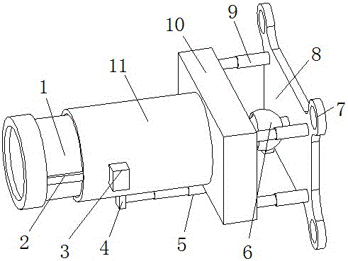
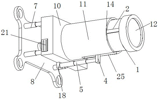
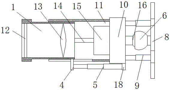
[0018] see Figure 1-4 , the present invention provides a technical solution: a monitoring camera with adjustable focal length, including a mounting plate 8, the center of one side of the mounting plate 8 is connected with a rotating connecting shell 6 through a connecting column, the rotating connecting shell 6 is a hemispherical structure, and The inside of the rotating connecting shell 6 is provided with a rotating connecting ball 16 which is connected with...


PUM


Abstract

The invention discloses a monitoring camera with an adjustable focal length. The monitoring camera comprises an installing plate installing plate. The center of one side of the installing plate is connected with a rotary connecting housing through a connecting column. The rotary connecting housing is of a semispherical structure. A rotary connecting ball is connected inside the rotary connecting housing in a rotary manner. One side of the rotary connecting ball is connected with the center of one side of a supporting case through a connecting column. A lens is driven by a first electric telescoping rod to move. The moving of the lens enables a focus of the lens in a camera device to be adjusted. The monitoring camera can be connected with external equipment through a WIFI connector, and can be operated in a remote manner. The monitoring camera has a simple structure, is easy to operate, enables shot frames to be clearer, enables shot frames to be saved, and is more convenient to adjust in angle. Moreover, shot frames can be transmitted to a mobile device, so that remote monitoring is more convenient.

Description

technical field [0001] The invention relates to the technical field of surveillance camera, in particular to a surveillance camera with adjustable focal length. Background technique [0002] The current monitoring works through cameras. There are many cameras, and they are controlled by a computer. It is very inconvenient to monitor the camera and the picture is not clear. Therefore, there are surveillance cameras on many occasions. It is a quasi-camera used in security. Its pixel and resolution are much higher than that of a computer video head, and lower than that of a professional digital camera or DV machine. The current surveillance camera is only a single video capture device and does not have the function of data storage. , therefore, it is necessary to manually monitor the imaging picture in real time to ensure the safety of the environment. Therefore, it is time-consuming and labor-intensive, and the work efficiency is not high. Moreover, the existing monitoring cam...

Claims


Application Information

Patent Timeline
Patent Type & Authority Applications(China)
IPC IPC(8): H04N5/225G03B13/32G03B7/18
CPCG03B7/18G03B13/32H04N23/50
Inventor 陈锐涛
Owner GUANGZHOU ZHONGYUAN NETWORK TECH CO LTD
Why Eureka
Try Eureka