Humidification agitator

A technology for mixers and mixing drums, which is applied to mixer accessories, mixers with rotating agitation devices, mixers, etc., can solve problems such as difficulties in production and maintenance, broken blades, and scaling of blades, and is beneficial to mixing efficiency and effect, the effect of uniform force

Inactive Publication Date: 2017-06-09
HENGYANG SHUANGYAN TRANSPORTATION MACHINERY
View PDF3 Cites 3 Cited by
  • Summary
  • Abstract
  • Description
  • Claims
  • Application Information

AI Technical Summary

Problems solved by technology

Ordinary humidifying mixers have certain defects. When the conveyed materials have certain bonding properties, especially in the case of uneven mixing of water and materials, the mixing blades are easily bonded by the materials, causing the blades to be surrounded by the adhesives and form fouling. , the longer the running time, the greater the adhesion scale and the higher the hardness, resulting in reduced conveying capacity and reduced output. In severe cases, the blade breaks, the motor trips due to overload, and it is very difficult to clean up the adhesive on the blade.
[0003] For example, the material of the flue gas desulfurization system of a thermal power plant contains quicklime, gypsum, fly ash, etc. and has a certain humidity. The blade scaling of the humidifying mixer often occurs during the use of the flue gas desulfurization material delivery system of the power plant. The more fouling and the higher the strength, the blades will eventually break, the material delivery will be reduced, and the system will be stopped for maintenance, which will bring great difficulties to production and maintenance.

Method used


Image

  • Humidification agitator
  • Humidification agitator

Examples


specific Embodiment

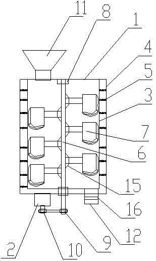
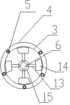
[0017] to combine figure 1 A humidifying mixer shown includes a vertically arranged cylindrical mixing drum 1 and a drive motor 2. The mixing drum 1 includes an inner drum 3 and an outer drum 4. The inner drum 3 is sleeved in the outer drum 4 and arranged concentrically. A spring 5 is arranged between the cylinder 3 and the outer cylinder 4. The inner cylinder 4 is an elastic rubber cylinder. The center of the inner cylinder 4 is vertically provided with a stirring shaft 6. The stirring shaft 6 is provided with a stirring blade 7. Both ends are fixed on the mixing drum through bearings 8, the lower end of the stirring shaft 3 runs through the mixing drum 1, a driven pulley 9 is arranged on the stirring shaft 6 outside the mixing drum 1, the driving motor 2 is arranged under the mixing drum 1, and the driving motor 2 The rotating shaft is provided with the driving pulley 10 that cooperates with the driven pulley 9, a belt is provided between the driven pulley 9 and the driving ...


PUM


Abstract

The invention discloses a humidification agitator which comprises a vertically arranged cylindrical agitating barrel and a driving motor, wherein the agitating barrel comprises an inner barrel and an outer barrel; the inner barrel is arranged in the outer barrel in a sleeving manner, and the inner barrel and the outer barrel are concentrically arranged; springs are arranged between the inner barrel and the outer barrel; the inner barrel is an elastic rubber barrel; an agitating shaft is vertically arranged at the center of the inner barrel; agitating blades are arranged on the agitating shaft; the upper and lower ends of the agitating shaft are both fixed on the agitating barrel through bearings; the lower end of the agitating shaft penetrates through the agitating barrel; a driven belt wheel is arranged at a position, which is located outside the agitating barrel, on the agitating shaft; the driving motor is arranged below the agitating barrel; a driving belt wheel matched with the driven belt wheel is arranged on a rotating shaft of the driving motor; a material feeding opening is formed in the upper end of the agitating barrel; a material outlet is formed in the lower end of the agitating barrel. The humidification agitator has the advantages that the agitating efficiency is high, the structure is simple, and the blades are difficult to break and damage.

Description

technical field [0001] The invention relates to the field of mixers, in particular to a humidifying mixer. Background technique [0002] The commonly used humidifying mixer includes a power device composed of a motor and a reduction wheel. The power device is connected to the stirring shaft in the mixing drum. The stirring shaft extends to the outside of the mixing drum and is supported by a bearing seat. The stirring shaft can be one or two parallel Arrangement, the stirring shaft is provided with stirring blades, and when the stirring shaft drives the stirring blades to rotate, it can stir and push the material forward to achieve the purpose of conveying. The mixing cylinder is equipped with a material inlet, a material outlet and a water inlet. It is to add water to play the role of humidification when the mixer is running, and the material is humidified and stirred evenly, and then discharged from the discharge port. Ordinary humidifying mixers have certain defects. Whe...

Claims


Application Information

Patent Timeline
Patent Type & Authority Applications(China)
IPC IPC(8): B01F7/18B01F7/24B01F15/00
Inventor 伍增产范涛
Owner HENGYANG SHUANGYAN TRANSPORTATION MACHINERY
Why Eureka
Try Eureka