
Automatic tool change detection encoder for CNC (Computer Numerical Control) machine tool

A technology for detecting encoders and machine tools. It is used in manufacturing tools, measuring/indicating equipment, metal processing mechanical parts, etc., and can solve problems such as failure to accurately control mechanism control, difficulty in adjusting cam angle, and delay in starting or stopping.

Inactive Publication Date: 2017-06-09
湖南衡泰机械科技有限公司
View PDF4 Cites 2 Cited by
  • Summary
  • Abstract
  • Description
  • Claims
  • Application Information

AI Technical Summary

Problems solved by technology

[0004] The method of using the circular wheel 12 to cooperate with the proximity switch 13 to control each mechanism is a purely mechanical method. Often due to factors such as slack chains, displacement of the circular wheel 12, and out-of-focus detection distance of the proximity switch 13, the mechanism control cannot be accurately controlled, such as starting Or stop delay or failure, etc., and when installing, correcting, repairing or reinstalling, it is very difficult to adjust the angle of each cam, which usually can only be completed by experienced technicians

Method used


Image

  • Automatic tool change detection encoder for CNC (Computer Numerical Control) machine tool
  • Automatic tool change detection encoder for CNC (Computer Numerical Control) machine tool
  • Automatic tool change detection encoder for CNC (Computer Numerical Control) machine tool

Examples


Embodiment Construction

[0019] In order to achieve the above-mentioned purpose, the technical means and mechanism adopted by this patent are now described in detail as follows:

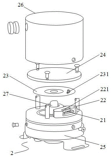
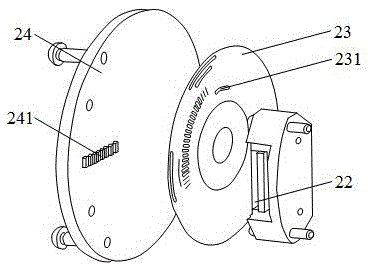
[0020] Please refer to figure 2 and image 3 , respectively are the three-dimensional exploded view and partial schematic diagram of the embodiment. It can be clearly seen from the figure that the CNC machine tool automatically switches the tool to the detection encoder 2, which is an electronic CNC machine tool that can be directly installed on the main shaft or the end of a specific rotating shaft. The automatic tool change detection encoder 2 includes: a light emitting element 21 , a photomask 22 , a grating wheel 23 and a light receiving and processing device 24 .

[0021] The light emitting element 21 emits a beam of light. In this embodiment, the light emitting element 21 is a light emitting diode.

[0022] The light cover 22 is covered on the light emitting element 21, and the light cover 22 is provided with a hole...


PUM


Abstract

The invention relates to an automatic tool change detection encoder for a CNC(Computer Numerical Control) machine tool. The automatic tool change detection encoder for the CNC machine tool comprises a light emitting element, a photo mask, a grating wheel and a light receiving and processing device. The light emitting element emits light. The photo mask on the light emitting element is provided with a hole for the light passing through. The grating wheel can rotate and is provided with a complex signal hole arranged in an annular shape. The light passes through the signal hole and corresponds to the signal to be detected by the automatic tool change mechanism. The light receiving and processing device receives the light and converts it to a control signal capable of controlling an automatic tool change tool. The automatic tool change detection encoder for a CNC machine tool has the advantages of no visual adjustment error and more accurate positioning accuracy.

Description

technical field [0001] The invention relates to an automatic tool change detection encoder, which refers to an electronic CNC machine tool automatic tool change detection encoder which can be directly installed at the end of a main shaft or a specific axis. Background technique [0002] In order to shorten the non-cutting time and improve productivity, most of the numerically controlled machine tools are equipped with automatic tool changer: ATC (Automatic tool changer) is used to improve the processing capacity of the machine tool and reduce the occupied space. ACT is driven by the rotating shaft. The arm claw cooperates with the movement of the mechanism, such as inserting the knife, clamping the knife, repositioning and other actions. [0003] refer to figure 1 As shown, it is the automatic tool change detection mechanism of CNC machine tool. The traditional control uses a cam box 11 connected to form various motion mechanisms for timing control. The cam box 11 is equip...

Claims


Application Information

Patent Timeline
IPC IPC(8): B23Q17/00B23Q17/22
CPCB23Q17/00B23Q17/22
Inventor 李孝良
Owner 湖南衡泰机械科技有限公司
Features
  • Generate Ideas
  • Intellectual Property
  • Life Sciences
  • Materials
  • Tech Scout
  • Unparalleled Data Quality
  • Higher Quality Content
  • 60% Fewer Hallucinations
Learn More