Robot platform for wind driven generator blade detection

A technology for wind turbines and robots, applied in the field of robot platforms, can solve the problems of large influence of weather and environment, low efficiency, unsafe worker's safety, etc., and achieves the effects of strong wall adaptability, simple control, and easy steering.

Inactive Publication Date: 2017-06-09
XIANGTAN UNIV
View PDF6 Cites 8 Cited by
  • Summary
  • Abstract
  • Description
  • Claims
  • Application Information

AI Technical Summary

Problems solved by technology

[0003] At present, there is a lack of professional equipment for the detection of wind turbine blades in China, and the traditional rope approach method is usually used. This kind of detection method similar to "spider man" is not only inefficient, but also cannot guarantee the safety of workers, and is affected by the weather. The environment has a greater impact

Method used


Image

  • Robot platform for wind driven generator blade detection
  • Robot platform for wind driven generator blade detection
  • Robot platform for wind driven generator blade detection

Examples


Embodiment 1

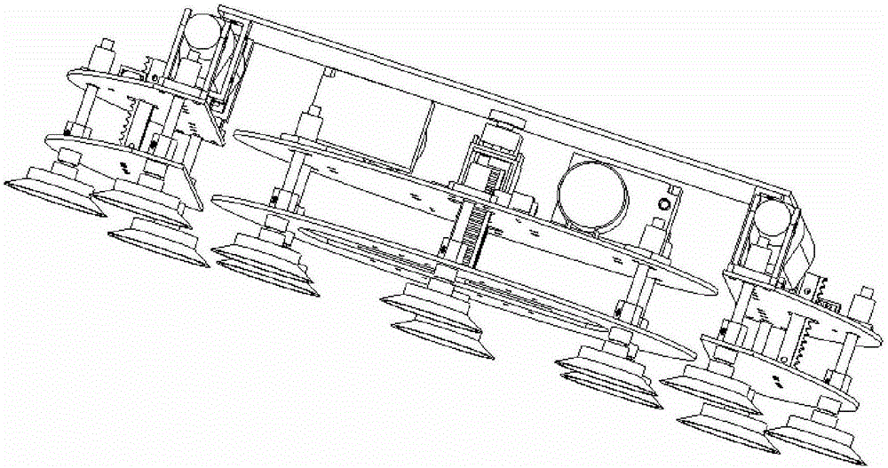
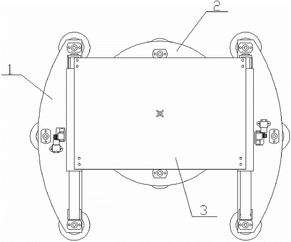
[0021] Embodiment 1, the present invention comprises connecting plate 3, two straight-ahead devices 1, steering device 2, straight-ahead device 1 is used for the forward and backward of robot, and steering device 2 is used for changing the straight-ahead direction of robot; The structure of described two straight-ahead devices 1 It is exactly the same, symmetrically installed on both sides below the connecting plate 3; the steering device 2 is installed at the center below the connecting plate 3; the straight running device 1 includes two support frames 19, two sliders 12, and two guide rails 15 , straight top plate 11, straight bottom plate 10, three suction cup assemblies, obstacle-crossing assembly, push-pull rod 17; the lower end of the support frame 19 is fixed on the slider 12, the slider 12 is set on the guide rail 15, and the guide rail 15 is fixed on the straight top plate 11 , the straight running top plate 11 is located directly above the straight running bottom plat...

Embodiment 2

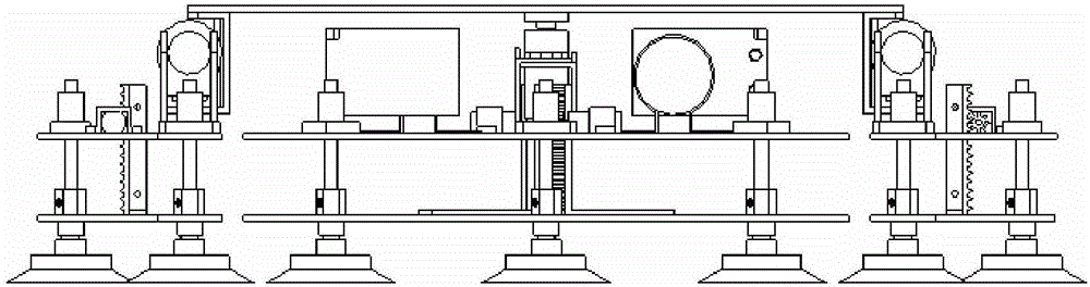
[0022] Embodiment 2, the obstacle-crossing assembly includes a DC deceleration motor 14, a gear, a rack 18, and a fixed plate 13; the DC deceleration is respectively installed on the straight top plate 11 and the turning top plate 21, and the DC deceleration motor 14 shaft ends are equipped with gears, The gear is connected with the rack 18, the rack 18 is installed on the fixed plate 13, and the fixed plate 13 is respectively installed on the straight bottom plate 10 and the steering bottom plate 22, and the forward and reverse rotation of the DC gear motor 14 can drive the corresponding sucker 9 to move up and down. Thereby, obstacle surmounting and adsorption are carried out. refer to Figure 1 to Figure 8 , all the other are with embodiment 1.

Embodiment 3

[0023] Embodiment 3, the suction cup assembly includes a suction cup 9, a ball hinge, fittings 5, and a linear bearing 6; the suction cup 9 is connected to one end of the ball hinge through threads, and the other end of the ball hinge is threaded to respectively go straight to the bottom plate 10 and turn to the fittings 5 ​​on the bottom plate 22 The lower ends are connected, and there is a ventilation hole 7 on the fitting 5, and the upper end of the fitting 5 is set in the linear bearing 6, and the linear bearing 6 is respectively installed on the straight top plate 11 and the turning top plate 21, and the upper end of the fitting 5 forms a rolling connection with the linear bearing 6, which can Reduce the resistance generated when the fitting 5 moves. refer to Figure 1 to Figure 8 , and the rest are the same as the above-mentioned embodiment.


PUM


Abstract

A robot platform for wind driven generator blade detection comprises a connecting plate (3), two straight walking devices (1) and a steering device (2). The structures of the two straight walking devices (1) are completely identical, and the two straight walking devices (1) are symmetrically mounted on the two sides of the lower surface of the connecting plate (3); the steering device (2) is mounted in the center of the lower surface of the connecting plate (3); each straight walking device (1) comprises two supporting frames (19), two sliding blocks (12), two guide rails (15), a straight walking top plate (11), a straight walking bottom plate (10), three suction cup assemblies, an obstacle crossing assembly and a push-pull rod (17). The steering device (2) comprises two micro vacuum pumps (24), a steering top plate (21), a steering bottom plate (22), six suction cup assemblies, two obstacle crossing assemblies and a steering engine (23). The robot platform is easy to steer, high in wall face adaptability, small in operation resistance and easy to control and has large application prospects in the field of wind driven generator blade detection.

Description

technical field [0001] The invention relates to the field of detection of blades of wind power generators, in particular to a robot platform for detection of blades of wind power generators. Background technique [0002] Wind turbine blades are one of the core components of wind turbines and a device for capturing wind energy, and their performance directly affects the performance of the entire system. Various media in the air are eroding the blades almost all the time, and regular inspections should be carried out every year to ensure the normal operation of the blades. [0003] At present, there is a lack of professional equipment for the detection of wind turbine blades in China, and the traditional rope approach method is usually used. This kind of detection method similar to the "spider man" is not only inefficient, but also cannot guarantee the safety of workers, and is affected by the weather. The environment has a greater impact. Therefore, researching a robot plat...

Claims


Application Information

Patent Timeline
Patent Type & Authority Applications(China)
IPC IPC(8): B62D57/032
CPCB62D57/032
Inventor 周友行贺洪江史宝强孔拓刘镇海
Owner XIANGTAN UNIV
Why Eureka
Try Eureka