A Method for Multidimensional Measurement of Finished Parts

A multi-dimensional, three-dimensional measurement technology, applied in the direction of measuring devices, instruments, etc., can solve the problems of disassembly and assembly of measuring machines, inconvenient handling, and bulky three-dimensional measuring machines, and achieve the effect of reducing deformation, lightening total weight, and light handling

Inactive Publication Date: 2017-06-09
重庆市路迪机械厂
View PDF0 Cites 0 Cited by
  • Summary
  • Abstract
  • Description
  • Claims
  • Application Information

AI Technical Summary

Problems solved by technology

[0004] In view of the measurement accuracy of the three-dimensional measuring machine in the prior art is greatly affected by the deformation of its upper arm, the vertical bar that needs to bear the bending moment on the three-dimensional measuring machine in the prior art is generally set to a larger size, so as to facilitate the deformation of the upper arm when it is stressed. The deformation is as small as possible, so the existing three-dimensional measuring machines are generally heavy, and the disassembly and transportation of the measuring machine are inconvenient for three-dimensional field measurement. The present invention provides a method for multi-dimensional measurement of finished parts

Method used


Image

  • A Method for Multidimensional Measurement of Finished Parts

Examples


Embodiment 1

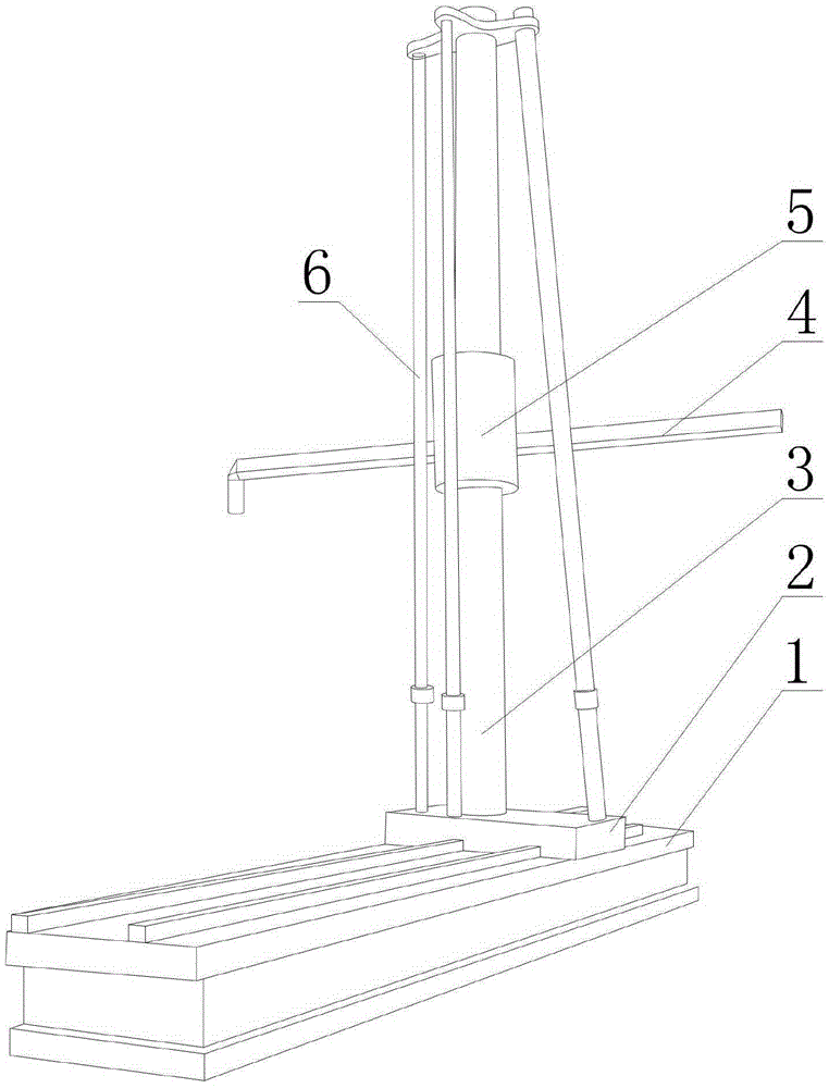
[0021] Such as figure 1 As shown, a method for multi-dimensional measurement of finished parts, including a base 1 provided with a slide rail, a sliding seat 2 arranged on the upper surface of the base 1 and engaged with the slide rail, fixed on the sliding seat The vertical bar 3 on the 2, the lifting part 5 which is sleeved on the vertical bar 3 and can move up and down along the length direction of the vertical bar 3, is arranged on the lifting part 5 and stretches out a length-adjustable horizontal bar relative to the lifting part 5. Rod 4, any end of the cross bar 4 is provided with a measuring head, and also includes a plurality of pull rods 6, the upper ends of the pull rods 6 are fixedly connected with the cross bar 4, and the lower ends of the pull rods 6 are fixed on the sliding seat 2, And the pull rods 6 are annularly arranged around the vertical rod 3; the pull rods 6 are two-section combined structures, at least one section of each pull rod 6 is a tubular struct...

Embodiment 2

[0025] The present embodiment is further limited on the basis of embodiment 1, as figure 1 As shown, in order to enable the pull rod 6 to serve the whole of the vertical rod 3 , the connection points between the pull rod 6 and the vertical rod 3 are located at the upper end of the vertical rod 3 .

[0026] As an implementation method that can reduce the weight of the vertical rod 3 and the tie rod 6 under the condition of satisfying the respective strengths of the vertical rod 3 and the tie rod 6, the vertical rod 3 and the tie rod 6 are all conical with the upper end diameter smaller than the respective lower end diameter pole.

[0027] As a structural form of the vertical rod 3 and the tie rod 6 that is convenient to obtain greater rigidity under the same material consumption, the vertical rod 3 and the tie rod 6 are both hollow structures.

Embodiment 3

[0029] This embodiment is further defined on the basis of any one of the solutions provided in the above embodiments, as a realization of the cross bar 4 that has good resistance to bending deformation under the same amount of material, and the cross bar 4 is vertical The longitudinal cross-section in its length direction is a rectangle whose width is smaller than the height.

[0030] As a further implementation of the cross bar 4 which has good resistance to bending deformation under the same material consumption, the cross bar 4 is a hollow bar.


PUM


Abstract

The invention discloses a method for multi-dimensional measurement of finished parts, which comprises a base provided with a slide rail, a sliding seat arranged on the upper surface of the base and engaged with the sliding rail, and a sliding seat fixed on the sliding seat. The vertical bar, the lifting part that is sleeved on the vertical bar and can move up and down along the length direction of the vertical bar, and the horizontal bar that is arranged on the lifting part and can be adjusted in length relative to the lifting part, and any end of the horizontal bar It is provided with a measuring head, and also includes a plurality of pull rods, the upper ends of the pull rods are fixedly connected with the cross bar, the lower ends of the pull rods are fixed on the sliding seat, and the pull rods are arranged around the vertical rod in a ring shape; the pull rods are Two-stage combined structure. The invention has a simple structure, is convenient for the disassembly and transportation of the three-dimensional measuring machine, and is also beneficial for reducing the deformation of the arm of the three-dimensional measuring machine, and is convenient for realizing the three-coordinate on-the-spot measurement of the workpiece.

Description

technical field [0001] The invention relates to the field of measuring instruments for geometric dimensions of equipment or components, in particular to a method for multi-dimensional measurement of finished parts. Background technique [0002] A three-dimensional measuring machine, also known as a three-dimensional measuring instrument, refers to an instrument that can express geometric shapes, lengths, and circumferential graduations within a hexahedral space. The three-coordinate measuring instrument can also define "a detector that can move in three directions and can move on three mutually perpendicular guide rails. The detector transmits signals in contact or non-contact. The displacement of the three axes measurement system (such as Grating ruler ) through a data processor or computer to calculate the points (x, y, z) of the workpiece and various functional measurement instruments". The measurement functions of the three-coordinate measuring instrument should include...

Claims


Application Information

Patent Timeline
Patent Type & Authority Applications(China)
IPC IPC(8): G01B21/00
Inventor 谭明聪
Owner 重庆市路迪机械厂
Why Eureka
Try Eureka