Denoising method and denoising device for near-infrared images

A near-infrared, image technology, applied in the field of image processing to suppress background noise and improve quality

Active Publication Date: 2017-06-09
湖南兴芯微电子科技有限公司
View PDF15 Cites 16 Cited by
  • Summary
  • Abstract
  • Description
  • Claims
  • Application Information

AI Technical Summary

Problems solved by technology

[0004] Embodiments of the present invention provide a near-infrared image denoising method and device to solve the problem that existing near-infrared image denoising methods cannot preserve image detail information under the premise of simplifying the calculation process

Method used


Image

  • Denoising method and denoising device for near-infrared images
  • Denoising method and denoising device for near-infrared images
  • Denoising method and denoising device for near-infrared images

Examples


Embodiment 1

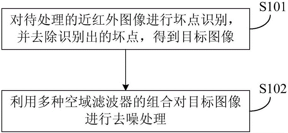
[0020] figure 1 The flow chart of the method for denoising a near-infrared image provided by Embodiment 1 of the present invention. This embodiment is applicable to removing noise in a near-infrared image. This method can be performed by a device for denoising a near-infrared image. The device can use implemented in software and / or hardware.

[0021] Such as figure 1 As shown, the denoising method of the near-infrared image in Embodiment 1 of the present invention specifically includes:

[0022] S101 , identifying bad pixels on the near-infrared image to be processed, and removing the identified bad pixels, to obtain a target image.

[0023] The near-infrared image is different from other images, and there is relatively large noise, and the more obvious noise is called a bad point, which refers to the point where the gray value of the pixel in the near-infrared image is obviously different from that of the surrounding pixels. Identification and removal will affect the denoi...

Embodiment 2

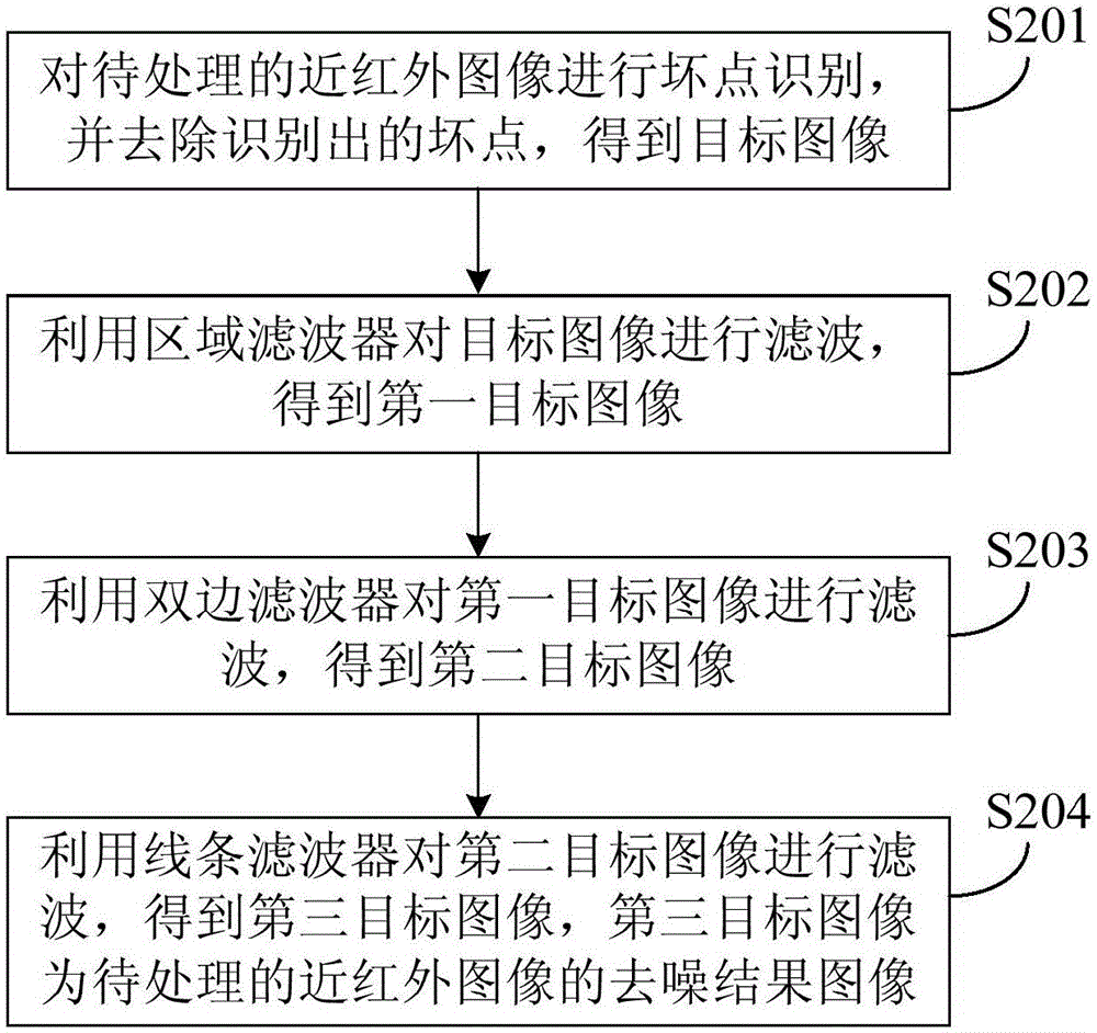
[0036] figure 2 It is a flow chart of the denoising method for near-infrared images provided by Embodiment 2 of the present invention. Embodiment 2 is based on Embodiment 1. The combination of various spatial domain filters and the combination of various spatial domain filters are used to optimize the target image. The operation of performing denoising processing will be further described.

[0037] In the second embodiment, the combination of multiple spatial filters preferably includes a combination of three types of filters: a regional filter, a bilateral filter and a line filter. It should be noted that, the embodiment of the present invention does not impose any limitation on the sequence of the above three filter combinations.

[0038] preferred, such as figure 2 As shown, the method of the second embodiment of the present invention specifically includes:

[0039] S201. Identify bad pixels on the near-infrared image to be processed, and remove the identified bad pixe...

Embodiment 3

[0073] Figure 5 It is a schematic structural diagram of a near-infrared image denoising device in Embodiment 3 of the present invention, which is applied to remove noise in a near-infrared image. Such as Figure 5 As shown, the near-infrared image denoising device 1 according to Embodiment 3 of the present invention includes a dead point identification module 10 and a denoising module 11 .

[0074] Wherein, the bad point identification module 10 is used for identifying bad points in the near-infrared image to be processed, and removing the identified bad points to obtain a target image.

[0075] Specifically, the bad point identification module 10 includes:

[0076] The first mean value calculation unit is used to use each pixel of the near-infrared image to be processed as a central pixel, and calculate the average value of the gray value of all pixels in the neighborhood of each central pixel based on the bad point identification template;

[0077] The first difference c...


PUM


Abstract

The embodiment of the invention discloses a denoising method and a denoising device for near-infrared images. The method comprises the following steps of subjecting a to-be-processed near-infrared image to bad point identification, removing identified bad points to obtain a target image, and subjecting the target image to denoising treatment by adopting the combination of multiple spatial filters. According to the embodiments of the invention, the above near-infrared image is subjected to bad point treatment and then the image obtained after the bad point treatment is subjected to denoising treatment by adopting the combination of multiple spatial filters. In this way, not only the background noise of the near-infrared image is effectively suppressed, but also the edge and detail information of the near-infrared image is maximally preserved. The quality of the near-infrared image is improved.

Description

technical field [0001] Embodiments of the present invention relate to image processing technologies, and in particular, to a method and device for denoising a near-infrared image. Background technique [0002] Near-infrared imaging technology realizes image acquisition under low-light conditions, such as night shooting for surveillance cameras. In addition, near-infrared imaging technology can also be used in emerging fields such as iris recognition, so it has received more and more attention and attention. However, due to the physical defects of the near-infrared image sensor, the noise of the near-infrared image is large, the gray scale is concentrated, and the contrast is low, which makes the visual effect of the near-infrared image very poor, and it is necessary to denoise the near-infrared image. [0003] At present, the commonly used denoising methods include methods based on image space domain and methods based on frequency domain. Among them, the filtering methods b...

Claims


Application Information

Patent Timeline
Patent Type & Authority Applications(China)
IPC IPC(8): G06T5/00
CPCG06T5/003G06T2207/10048G06T2207/20024
Inventor 沈超
Owner 湖南兴芯微电子科技有限公司
Why Eureka
Try Eureka