Imaging method and imaging device of microlens array
A technology of a microlens array and an imaging method, which can be used in image communication, parts of color TVs, parts of TV systems, etc., and can solve problems such as uneven brightness distribution
- Summary
- Abstract
- Description
- Claims
- Application Information
AI Technical Summary
Problems solved by technology
Method used
Image
Examples
no. 1 example
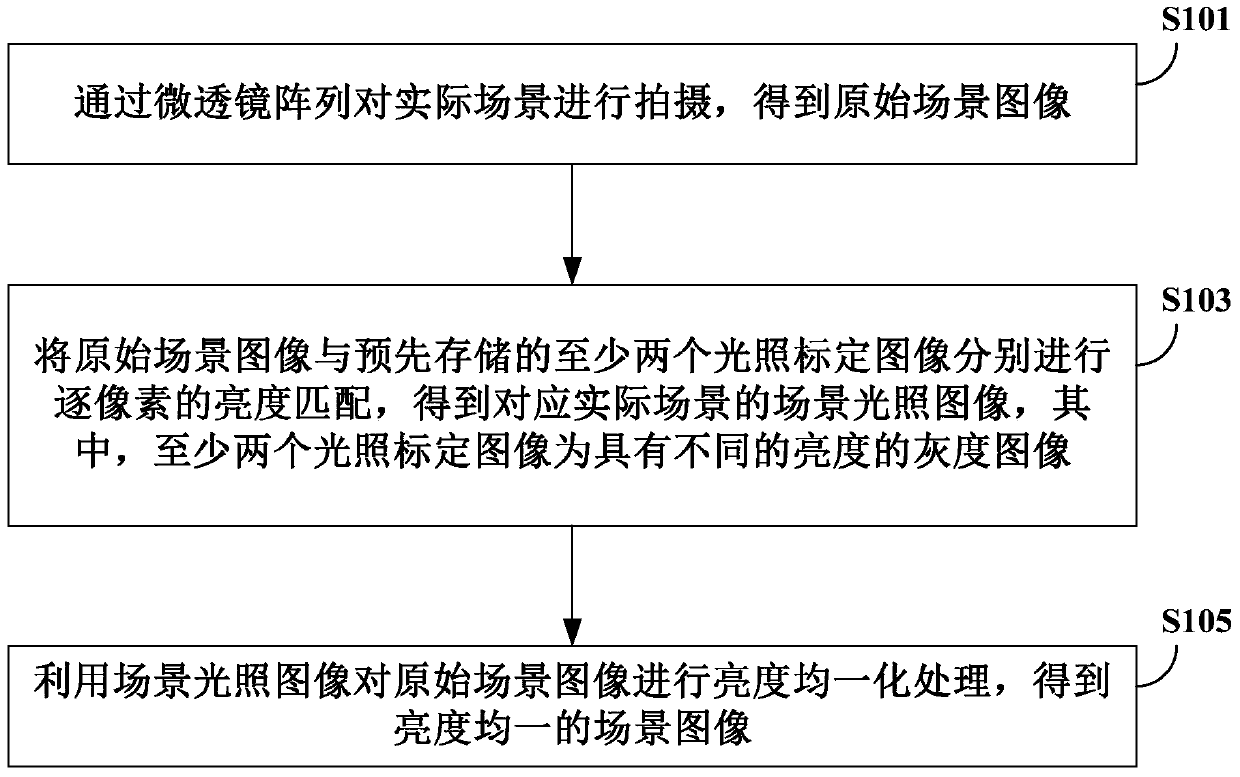
[0089] see figure 1 , the figure shows the flow chart of the imaging method of the microlens array in the first embodiment, the method can be applied to light field cameras, compound eye cameras and microscopic imaging systems with large fields of view, and the specific steps included in the method are as follows:
[0090] Step S101 , photographing an actual scene through a microlens array to obtain an original scene image.
[0091] Specifically, a microlens array is used to shoot an actual scene to obtain an original scene image. The original scene image refers to an image acquired during actual scene shooting. If the actual scene is photographed by the microlens array in the existing way, there is a phenomenon that the center is bright and the periphery is dark in the image formed by each microlens.
[0092] Step S103, performing pixel-by-pixel brightness matching on the original scene image and at least two pre-stored lighting calibration images to obtain a scene lighting...
no. 2 example
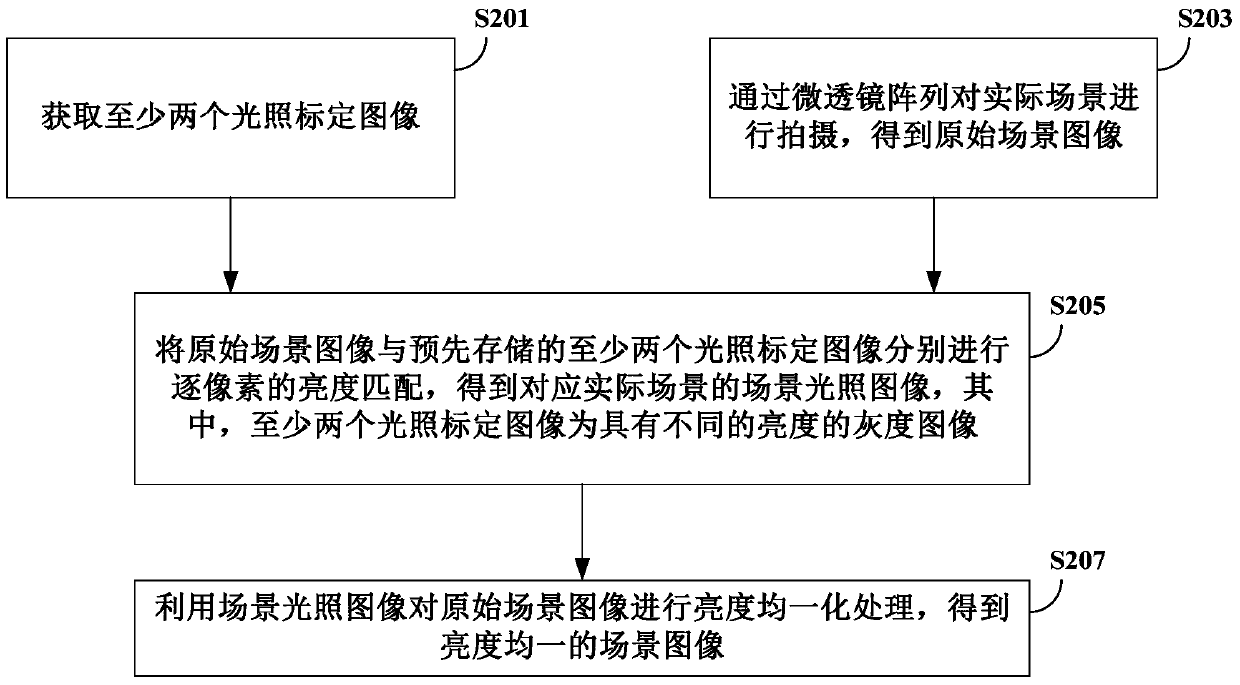
[0098] see figure 2 , the figure shows the flow chart of the imaging method of the microlens array in the second embodiment. This method can be applied to light field cameras, compound eye cameras and microscopic imaging systems with large fields of view. The specific steps included in the method are as follows:
[0099] Step S201, acquiring at least two illumination calibration images.
[0100] Specifically, through the microlens array, under the same exposure time and the same image sensor configuration, at least two illumination calibration images are obtained for a uniform light source with gradually changing illumination intensity; at least two illumination calibration images are stored in the storage device , enter step S205.
[0101] Step S203 , shoot the actual scene through the microlens array to obtain the original scene image, and proceed to step S205 .
[0102] Specifically, a microlens array is used to shoot an actual scene to obtain an original scene image. T...
no. 3 example
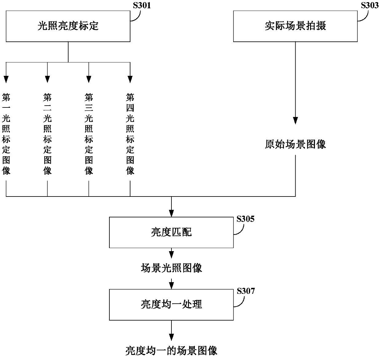
[0116] see image 3 , the flow chart of the imaging method of the microlens array in the third embodiment is shown in the figure, and the specific steps are as follows:
[0117] Step S301, calibration of illumination brightness, and then proceed to step S305.
[0118] Specifically, using a microlens array, under the same exposure time and the same image sensor configuration, a series of illumination images are obtained for a uniform light source with gradually changing illumination intensity, which is used to correct uneven brightness during actual shooting; this step can When the microlens array is finalized, a series of illumination calibration images acquired (such as the first illumination calibration image, the second illumination calibration image, the third illumination calibration image and the fourth illumination calibration image) are stored in the storage device. The original scene image is used for brightness matching, and there is no need to perform this step aga...
PUM
 Abstract
Description
Claims
Application Information
 - R&D
- Intellectual Property
- Life Sciences
- Materials
- Tech Scout
- Unparalleled Data Quality
- Higher Quality Content
- 60% Fewer Hallucinations
Browse by: Latest US Patents, China's latest patents, Technical Efficacy Thesaurus, Application Domain, Technology Topic, Popular Technical Reports.
© 2025 PatSnap. All rights reserved.Legal|Privacy policy|Modern Slavery Act Transparency Statement|Sitemap|About US| Contact US: help@patsnap.com


