
A method of using a video optical transceiver

An optical transceiver and video technology, applied in the field of video optical transceivers, can solve the problem of low stability of luminous power, and achieve the effects of avoiding optical fiber transmission speed, good waterproof protection, and good waterproof function

Inactive Publication Date: 2017-06-09
重庆健旺科技有限公司
View PDF0 Cites 0 Cited by
  • Summary
  • Abstract
  • Description
  • Claims
  • Application Information

AI Technical Summary

Problems solved by technology

[0004] The invention provides a method for using a video optical transceiver to solve the problem of low stability of laser luminous power and achieve the purpose of improving the service life of the laser

Method used


Image

  • A method of using a video optical transceiver
  • A method of using a video optical transceiver

Examples


Embodiment 1

[0020] Such as figure 1 As shown, in the present invention, the image information or data transmitted by the front-end equipment first enters the digital-to-analog converter through the input interface of the optical transceiver transmission module, and the digital-to-analog converter converts it into an analog signal, and the encoder encodes the analog signal to facilitate line transmission. Code stream, and then enter the transmitter, the transmitter converts the electrical signal into an optical signal, and transmits it to the optical fiber through the output interface. The waterproof mechanism set on the rack can ensure the normal operation of the optical transceiver in a humid environment; especially for tunnels , The transmission of data in the mine has a good waterproof protection; the card slots set on the frame are respectively adapted to the output port of the transmitter, the front-end data interface, and the audio and video interface, which is convenient for the ov...

Embodiment 2

[0023] Such as figure 1 As shown, this embodiment is based on Embodiment 1, the sending module further includes a time division multiplexer, and the encoder is connected to the time division multiplexer. The set time-division multiplexer can make multiple information flows into one high-speed information flow for rapid transmission.

Embodiment 3

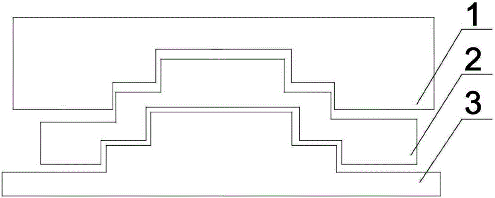
[0025] Such as figure 2 As shown, this embodiment is based on Embodiment 1, the frame includes an upper casing 1 and a lower casing 3, the upper casing 1 and the lower casing 3 are connected by bolts, and the waterproof mechanism includes a Fitted tooth track and devulcanized rubber pad 2 at the junction of shell 1 and lower shell 3 . The fitting tooth track is a tooth-shaped structure formed by the concave part of the upper casing 1 and the protruding part of the lower casing 3. When sealing, place the devulcanized rubber pad 2 between the upper casing 1 and the lower casing 3 and then connected by bolts. Compared with the devulcanized rubber pad 2, after the ordinary rubber pad is used for a long time, the sulfide contained in it will corrode the frame, and the sealing effect will be greatly weakened.


PUM


Abstract

The invention discloses a method for using a video optical transceiver. First, the image information or data transmitted by the front-end equipment enters the digital-to-analog converter through the input interface of the optical transceiver transmission module, and the digital-to-analog converter converts it into an analog signal, and the encoder converts the analog The signal encoding can facilitate the code stream of line transmission, and then enter the transmitter. The transmitter converts the electrical signal into an optical signal and transmits it to the optical fiber through the output interface. The waterproof mechanism set on the rack can ensure the normal operation of the optical transceiver in a humid environment. work; especially for the transmission of data in tunnels and mines, it has a good waterproof protection; the card slots set on the rack are respectively adapted to the output port of the transmitter, the front-end data interface, and the audio and video interface, which is convenient for optical transceivers. The whole is sealed.

Description

technical field [0001] The invention relates to computer network transmission technology, in particular to a method for using a video optical transceiver. Background technique [0002] The video optical transceiver converts 1-channel to multiple-channel analog video signals through various codes Cheng Guang signal through optical fiber Media to transmit equipment. because video signal In the process of converting into an optical signal, two technologies, analog conversion and digital conversion, are used, so there are analog optical transceivers and digital optical transceivers on the market. The analog optical transceiver adopts baseband / AM / FM / PFM modulation technology to transmit image signals. The transmitting end first performs PFM modulation on the analog video signal, and then performs electrical-optical conversion. The optical signal is transmitted to the receiving end for optical-electrical conversion, and then Perform PFM demodulation and reply video signal. ...

Claims


Application Information

Patent Timeline
IPC IPC(8): H04N7/22
Inventor 聂建仙
Owner 重庆健旺科技有限公司
Learn More