Passive energy-storage ankle joint and foot mechanism for power-assisted exoskeletons of lower limbs

An ankle joint and exoskeleton technology, which is applied to passive exercise equipment, manipulators, program-controlled manipulators, etc., can solve the problem that the performance of tension springs or compression springs is not clear, the boosting effect is not optimal, and the flexibility of the foot mechanism is poor. and other problems, to achieve the effect of coordinated movement trend, compact structure, and reduced weight of the mechanism

Active Publication Date: 2017-06-13
SOUTHEAST UNIV +1
View PDF12 Cites 15 Cited by
  • Summary
  • Abstract
  • Description
  • Claims
  • Application Information

AI Technical Summary

Problems solved by technology

[0004] The lower limb power-assisted exoskeleton ankle joint and foot mechanism consist of a rigid plate that can support the wearer's entire foot combined with a mechanical ankle joint with 1, 2 or 3 degrees of freedom. The mechanical ankle joints usually use motors, hydraulic cylinders, and air cylinders for each degree of freedom. Such foot mechanisms are poor in flexibility, difficult to control, extremely demanding on the control system, and relatively high in cost; some new ankle mechanisms arrange a pair of springs in front and back to reduce the wearer's ankle joint in the sagittal plane. force, but the fixed end of the spring is always fixed on the foot base, the performance of the tension spring or compression spring is not clear during the movement, and there is two-way spring resistance, the assist effect is not optimal

Method used


Image

  • Passive energy-storage ankle joint and foot mechanism for power-assisted exoskeletons of lower limbs
  • Passive energy-storage ankle joint and foot mechanism for power-assisted exoskeletons of lower limbs
  • Passive energy-storage ankle joint and foot mechanism for power-assisted exoskeletons of lower limbs

Examples


Embodiment Construction

[0030] The technical solution of the present invention will be described in detail below in combination with the embodiments and the accompanying drawings.

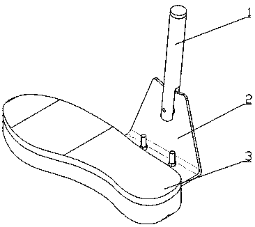
[0031] like figure 1 As shown in the overall structure diagram, a passive energy storage ankle joint mechanism for lower limb power-assisted exoskeleton includes an ankle joint unit 1 , a foot side panel unit 2 and a foot pad unit 3 . The interior of the ankle joint unit 1 realizes one degree of freedom movement in the sagittal plane, and is connected with the foot side panel unit 2; the foot side panel unit 2 is connected with the foot pad unit 3.

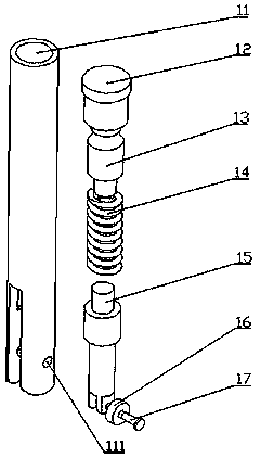
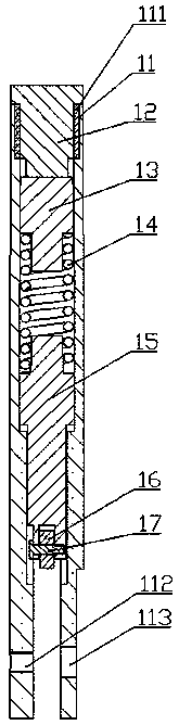
[0032] like figure 2 Ankle unit exploded view and image 3 The front view of the full section of the ankle joint unit, the ankle joint unit 1 includes the calf rod 11, the ankle joint thrust fixing rod 12, the ankle joint thrust rod 13, the compression spring 14, the ankle joint guide rod 15, the pulley 16 and the pulley shaft 17; The internal thread 111 at the upper end ...


PUM


Abstract

The invention discloses a passive energy-storage ankle joint and foot mechanism for power-assisted exoskeletons of lower limbs. The passive energy-storage ankle joint and foot mechanism comprises an ankle joint unit, a foot-side panel unit and a foot pad unit, wherein the ankle joint unit comprises a crus rod and a compression spring and an ankle-joint guide rod; the compression spring and the ankle-joint guide rod are arranged in the crus rod; the foot-side panel unit comprises a foot-side panel, a foot pad and a wavy spring body; the foot-side panel comprises a side plate and a bottom plate; the foot pad and the wavy spring body are arranged at the lower end of the bottom plate; an arc-shaped surface is arranged on the side plate; the lower end of the crus rod is hinged on the side plate; and the lower end of the ankle-joint guide rod is contacted with the arc-shaped surface under the action of the compression spring and moves along the arc-shaped top surface. The passive energy-storage ankle joint and foot mechanism disclosed by the invention has the advantages that the foot structure of a human body, the human body and the mass and the inertial action of the exoskeletons are fully utilized, the passive energy storage of the ankle joint and the bottom-touching energy storage of the bow-shaped sole in the traveling process are realized, the wearing is comfortable, the energy storage is low and the practicability is strong.

Description

technical field [0001] The invention relates to a passive energy storage ankle joint and a foot mechanism for lower limb power-assisted exoskeleton, belonging to the field of robot applications. Background technique [0002] Exoskeleton rehabilitation assisting robot is a robot automation device that assists or replaces rehabilitation physiotherapists to complete joint rehabilitation training, which is produced by combining robotics, automation technology and clinical rehabilitation medical technology. [0003] The human body has numerous joints, such as hip joints, knee joints, ankle joints, and wrist joints, among which the ankle joint is the joint closest to the ground and bears almost the weight of the entire body, especially when a person is jumping, running and When the body bears weight, the ankle joint bears a huge impact and load. The movement of the human ankle joint is mainly realized and restricted by the ligaments and Achilles tendon. According to the structure ...

Claims


Application Information

Patent Timeline
Patent Type & Authority Applications(China)
IPC IPC(8): A61H1/02B25J9/00B25J17/00
Inventor 王兴松朱智勇甘振波李伟强张毅
Owner SOUTHEAST UNIV
Why Eureka
Try Eureka