Full-automatic proportioning device and method of lubricating agent for thread throwing of ceramic fibers

A technology of ceramic fibers and lubricants, which is applied in the directions of lubricating compositions, chemical instruments and methods, mixers with rotary stirring devices, etc. Save operation steps and increase the effect of uniformity

Pending Publication Date: 2017-06-13
山东红阳高温节能材料股份有限公司
View PDF6 Cites 3 Cited by
  • Summary
  • Abstract
  • Description
  • Claims
  • Application Information

AI Technical Summary

Problems solved by technology

[0005] The technical task of the present invention is to address the above deficiencies, to provide a fully automatic proportioning device and method for lubricants for ceramic fiber spinning, to solve the problem of low precision in the proportioning of lubricants for ceramic fiber spinning and continuous production.

Method used


Image

  • Full-automatic proportioning device and method of lubricating agent for thread throwing of ceramic fibers
  • Full-automatic proportioning device and method of lubricating agent for thread throwing of ceramic fibers
  • Full-automatic proportioning device and method of lubricating agent for thread throwing of ceramic fibers

Examples


Embodiment 1

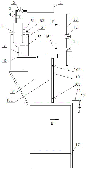
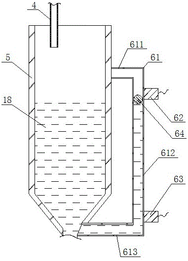
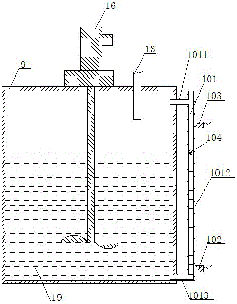
[0063] as attached figure 1 , attached figure 2 , attached image 3 And attached Figure 4 As shown, a fully automatic proportioning device for lubricant for ceramic fiber spinning of the present invention includes a support 17, a liquid level detection device, a stirring device 16, a controller 20, a water pipe 13, a liquid outlet pipe 11, and a top-to-bottom The lubricant container 1, the lubricant metering cup 5 and the upper container 9 arranged in sequence on the bracket 17, the lubricant metering cup 5 and the upper container 9 are provided with upper and lower ports arranged up and down, the lubricant container 1 and the lubricant The upper port of the lubricant metering cup 5 is connected up and down through the upper infusion tube 4, the lower port of the lubricant metering cup 5 and the upper port of the upper container 9 are connected up and down through the lower infusion tube 8, and the lower port of the upper container 9 is connected with the liquid outlet pip...

Embodiment 2

[0083] as attached Figure 5 , attached Image 6 And attached Figure 7 As shown, this embodiment is a further improvement on the basis of Embodiment 1. The difference between this embodiment and Embodiment 1 is: the upper container 9 is provided with a temperature detector I22 heating device I21, a temperature detector I22 heating device I21 Both are connected with the controller 20.

[0084] The temperature detector I22 is used to detect the temperature of the lubricant 18 and water in the upper container 9; the heating device I21 is an electric heating tube, which is used to heat the lubricant 18 and water in the upper container 9. When the temperature of the lubricant 18 and water in the upper container 9 is lower than the preset value, the lubricant 18 and water are heated by the heating device I21 to facilitate the complete dissolution of the lubricant 18 in the water.

[0085] Simultaneously, a nozzle 23 is communicated with the liquid outlet pipe 11, and when the lu...

Embodiment 3

[0095] as attached Figure 8 , attached Figure 9 And attached Figure 10 As shown, this embodiment is a further improvement on the basis of Embodiment 1. The difference between this embodiment and Embodiment 1 is that it also includes a lower container 26 and a liquid level detection device corresponding to the lower container 26, and the lower container 26 is arranged on On the bracket 17 and below the upper container 9, the lower container 26 is provided with an upper port and a lower port arranged up and down, and the upper port of the lower container 26 and the lower port of the upper container 9 communicate through the mixed liquid infusion tube 24, and the lower container 26 The lower port of the lower port is connected with the liquid outlet pipe 11, and the mixed liquid infusion pipe 24 is provided with an electric valve IV 25, and the liquid level detection device and the electric valve IV 25 are connected with the controller 20.

[0096] Wherein, the liquid level ...


PUM


Abstract

The invention discloses an full-automatic proportioning device and method of a lubricating agent for thread throwing of ceramic fibers, belongs to the field of proportioning devices of lubricating agents for thread throwing of ceramic fibers, aims to solve the technical problem that the conventional lubricating agent for thread throwing of the ceramic fibers has the defects of low proportioning accuracy and impossibility in continuous production. The full-automatic proportioning device comprises a bracket, liquid level detection devices, a stirring device, a controller, a water tube, a liquid outlet tube, a lubricating agent container, a lubricating agent metering cup and an upper container, wherein the lubricating agent container, the lubricating agent metering cup and the upper container are arranged on the bracket; the lubricating agent metering cup and the upper container are provided with upper ports and lower ports which are arranged one above the other; the upper port of the upper container communicates with the water tube which is positioned above the upper port of the upper container; the lower port of the upper container communicates with the liquid outlet tube; the liquid outlet tube, the water tube and liquid delivery tubes are provided with switch valves; the lubricating agent metering cup and the upper container correspond to the liquid level detection devices respectively; the liquid level detection devices and the stirring device are connected with the controller. The method is used for preparing lubricating liquid by using the full-automatic proportioning device of the lubricating agent for thread throwing of the ceramic fibers.

Description

technical field [0001] The invention relates to the field of a lubricant proportioning device for ceramic fiber spinning, in particular to a fully automatic lubricant proportioning device and method for ceramic fiber spinning. Background technique [0002] The lubricant and water are mixed and stirred to obtain a lubricating liquid, and the lubricating liquid is added to the ceramic fiber when spinning the ceramic fiber. The appearance, color and softness of the ceramic fiber are related to the ratio of water and lubricant in the lubricating liquid during spinning. , when the amount of lubricant in the lubricating liquid is small, the color of the ceramic fiber is white and beautiful, but the softness becomes poor and the pulling force becomes low. When the amount of lubricant in the lubricating liquid is large, the softness of the ceramic fiber is good but the color is dark Black spots and spring spots, so preparing a suitable lubricating solution plays an important role in...

Claims


Application Information

Patent Timeline
Patent Type & Authority Applications(China)
IPC IPC(8): B01F7/16B01F15/00B01F15/02C10M177/00
CPCC10M177/00B01F27/80B01F35/2112B01F35/2142B01F35/71805B01F2101/39
Inventor 郑志永孙选
Owner 山东红阳高温节能材料股份有限公司
Why Eureka
Try Eureka