A flotation machine for flotation of coarse-grained materials

A flotation machine and coarse-grained technology, which is applied in the field of flotation machines, can solve the problems of small stirring force, easy to press the flotation cell, poor sorting effect of coarse-grained materials, etc. The effect of the chance of adhesion

Active Publication Date: 2020-05-01
BLUESTAR LEHIGH ENG INST CO LTD
View PDF7 Cites 0 Cited by
  • Summary
  • Abstract
  • Description
  • Claims
  • Application Information

AI Technical Summary

Problems solved by technology

[0002] According to the mineral processing theory, the optimal particle size of flotation is 0.019~0.15mm. At present, most of the flotation machines developed in China are mainly for the separation of this particle size range, but some ores (such as coal mines, potassium rock salts, etc.) ore, etc.) can basically achieve monomer dissociation at a coarser particle size (0.3~1.5mm), and can be directly fed into the flotation machine for sorting. To adapt to the flotation particle size of the conventional flotation machine, you need Continue to grind, which will cause additional energy consumption for ore sorting, and will reduce the dehydration efficiency of the final fine tailings. If a conventional flotation machine is used to process ores within the size range of 0.3~1.5mm, there will be flotation The stirring force of the machine is too small, the flotation cell is easy to press the cell, and the recovery rate of the concentrate is low. In order to solve the problem of poor separation effect of the conventional flotation machine in processing coarse-grained materials, the present invention designs a low energy consumption, A flotation machine specially designed for the separation of coarse-grained materials with good separation effect

Method used


Image

  • A flotation machine for flotation of coarse-grained materials
  • A flotation machine for flotation of coarse-grained materials
  • A flotation machine for flotation of coarse-grained materials

Examples


Embodiment 1

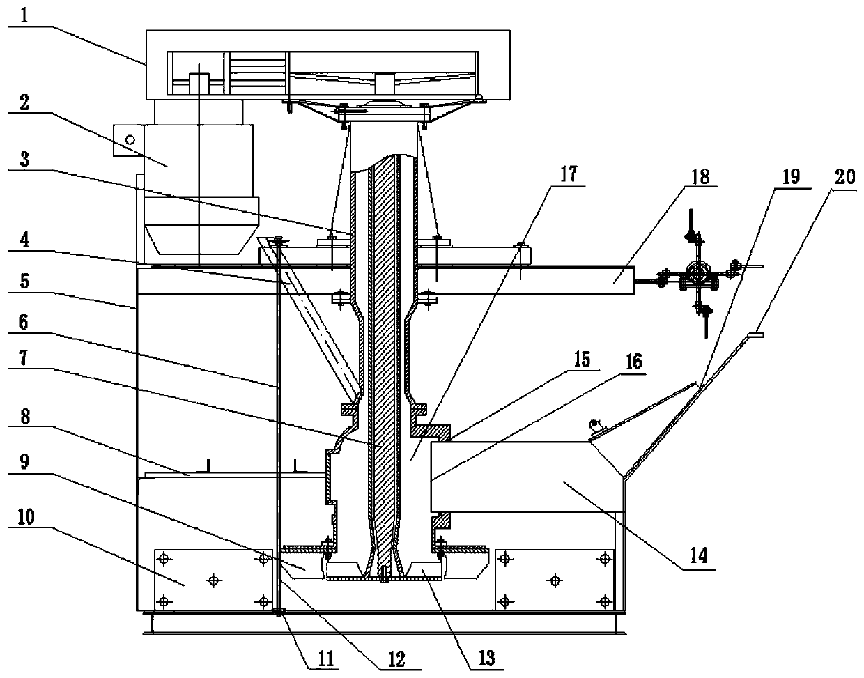
[0033] Embodiment 1, with reference to Figure 1-11 , a flotation machine used for flotation of coarse-grained materials, comprising a bracket 1 and a flotation cell body 5, an overflow weir 20 for foam overflow is arranged on one side of the flotation cell body, and an overflow weir is arranged above the overflow weir There is a bubble scraping device 18 for scraping foam, which is characterized in that it also includes:

[0034] The stirring mechanism includes a stirring rod 7 extending into the flotation cell body, the upper end of the stirring rod is connected with the driving device 2, and a stirring assembly is installed at the lower end of the stirring rod;

[0035] A sleeve 3 is sheathed on the stirring rod, and the annular chamber 17 formed between the sleeve 3 and the stirring rod 7 is used to transport air and ore pulp into the flotation cell body 5. The lower part is provided with at least one slurry inlet 15;

[0036] The circulation tank 14 is arranged under th...

Embodiment 2

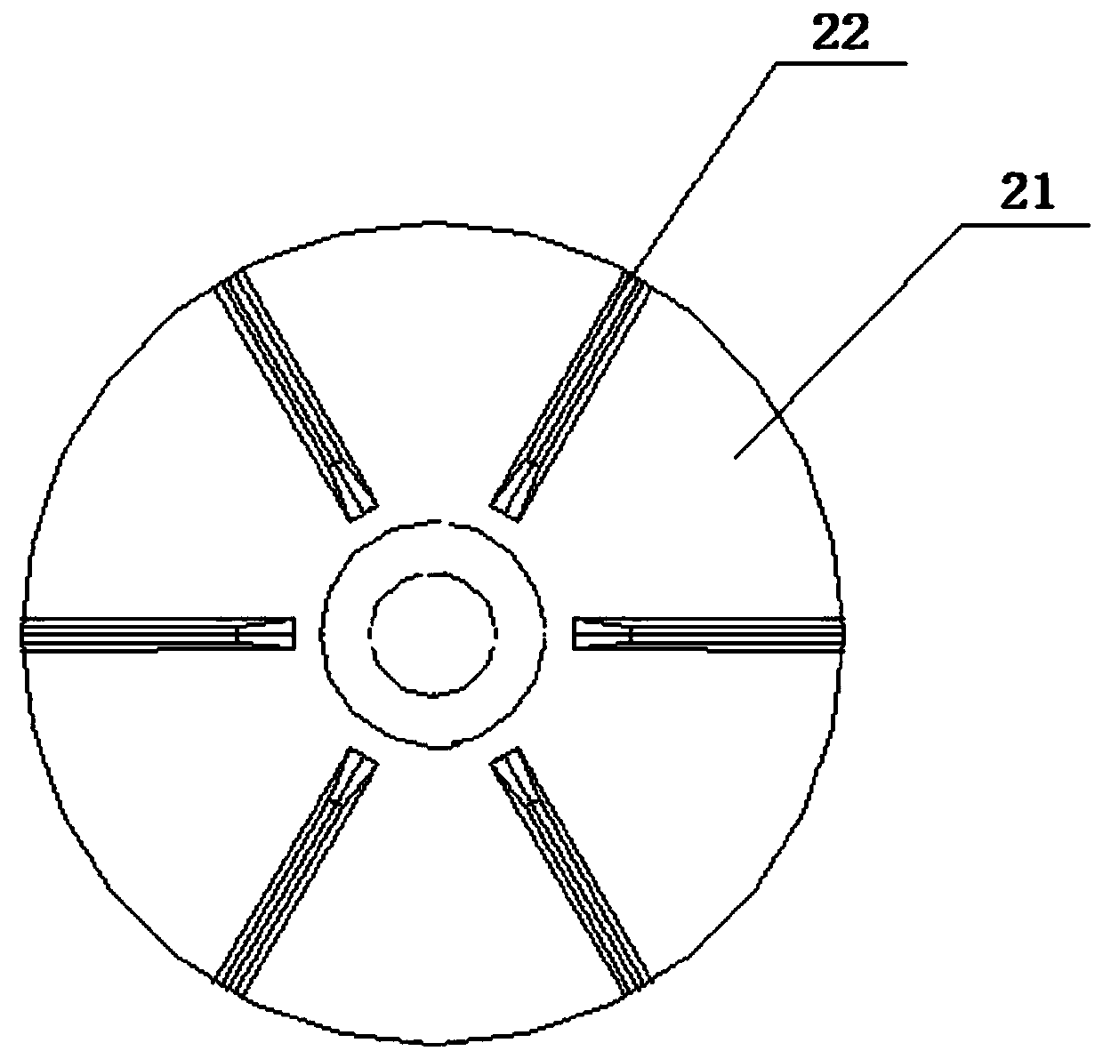
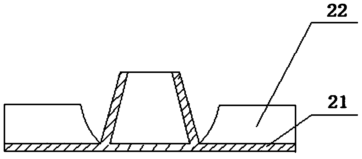
[0037] Embodiment 2, in a kind of flotation machine that is used for the flotation of coarse-grained material described in embodiment 1: described stirring assembly is arranged as stirring rotor 13, comprises disc-shaped rotor bottom plate 21 and several rotor blades 22, The rotor blades are mounted radially and annularly on the rotor bottom plate, and the rotor bottom plate is fixedly mounted on the bottom of the stirring rod; the ratio of the impeller diameter to the groove width of the stirring rotor is preferably set at 0.34-0.42.

Embodiment 3

[0038] Embodiment 3, in a kind of flotation machine used for the flotation of coarse-grained materials described in embodiment 1 or 2: a stirring stator 9 matched with a stirring rotor 13 is installed at the bottom of the sleeve 3, and the stirring stator It includes a disc-shaped stator base plate 23 and several stator blades 24, the stator blades are evenly distributed on the stator base plate in a ring shape, and each stator blade is deflected clockwise or counterclockwise by an angle of α, and the angle of α is preferably set to 20°- 40°, a stator reserved hole 25 for pulp flow is provided at the center of the stator bottom plate; the ratio of the impeller diameter to the groove width of the stirring stator is preferably set to 0.46-0.56.


PUM


Abstract

The invention relates to a flotation machine for coarse-grain material flotation. The flotation machine comprises a support and a flotation tank, wherein an overflow weir for foam overflowing is arranged on one side of the flotation tank. The flotation machine is characterized by further comprising a stirring mechanism and a circulating tank, the stirring mechanism comprises a stirring rod extending into the flotation tank, the upper end of the stirring rod is connected with a driving device, and a stirring assembly is mounted at the lower end of the stirring rod; the stirring rod is sleeved with a sleeve, an annular chamber formed between the sleeve and the stirring rod is used for conveying air and ore pulp into the flotation tank, the top end of the sleeve is connected with the support, and at least one pulp inlet is formed in the lower part of the sleeve; the circulating tank is arranged below the overflow weir, used for recovering the ore pulp flowing back from the overflow weir and communicated with the annular chamber. A good fluid environment is provided for separation of coarse-grain materials, the chance of adhesion of ore to bubbles is greatly increased, and the condition that fine-grain ore is not mineralized or mechanical entrainment occurs is effectively eliminated.

Description

technical field [0001] The invention relates to a flotation machine for ore separation, in particular to a flotation machine for coarse-grained material flotation. Background technique [0002] According to the mineral processing theory, the optimal particle size of flotation is 0.019~0.15mm. At present, most of the flotation machines developed in China are mainly for the separation of this particle size range, but some ores (such as coal mines, potassium rock salts, etc.) ore, etc.) can basically achieve monomer dissociation at a coarser particle size (0.3~1.5mm), and can be directly fed into the flotation machine for sorting. To adapt to the flotation particle size of the conventional flotation machine, you need Continue to grind, which will cause additional energy consumption for ore sorting, and will reduce the dehydration efficiency of the final fine tailings. If a conventional flotation machine is used to process ores within the size range of 0.3~1.5mm, there will be f...

Claims


Application Information

Patent Timeline
Patent Type & Authority Patents(China)
IPC IPC(8): B03D1/16B03D1/02
CPCB03D1/02B03D1/16
Inventor 田鹏杰林杰张守祥孙媛媛
Owner BLUESTAR LEHIGH ENG INST CO LTD
Why Eureka
Try Eureka