Continuous type separation equipment

A technology of separation equipment and transmission part, which is applied in the direction of solid separation, filter screen, grille, etc., which can solve the problems of separation, failure, and easy blockage of continuous working filter net, and achieve the effect of improving breeding efficiency and promoting separation

Inactive Publication Date: 2017-06-13
浙江众鑫新材料科技有限公司
View PDF1 Cites 7 Cited by
  • Summary
  • Abstract
  • Description
  • Claims
  • Application Information

AI Technical Summary

Problems solved by technology

[0006] The purpose of the present invention is to overcome the deficiencies of the prior art and overcome the problems of not being able to separate while transporting, continuous work and easy clogging of the filter screen to affect the quality of the feed

Method used


Image

  • Continuous type separation equipment
  • Continuous type separation equipment
  • Continuous type separation equipment

Examples


Embodiment 1

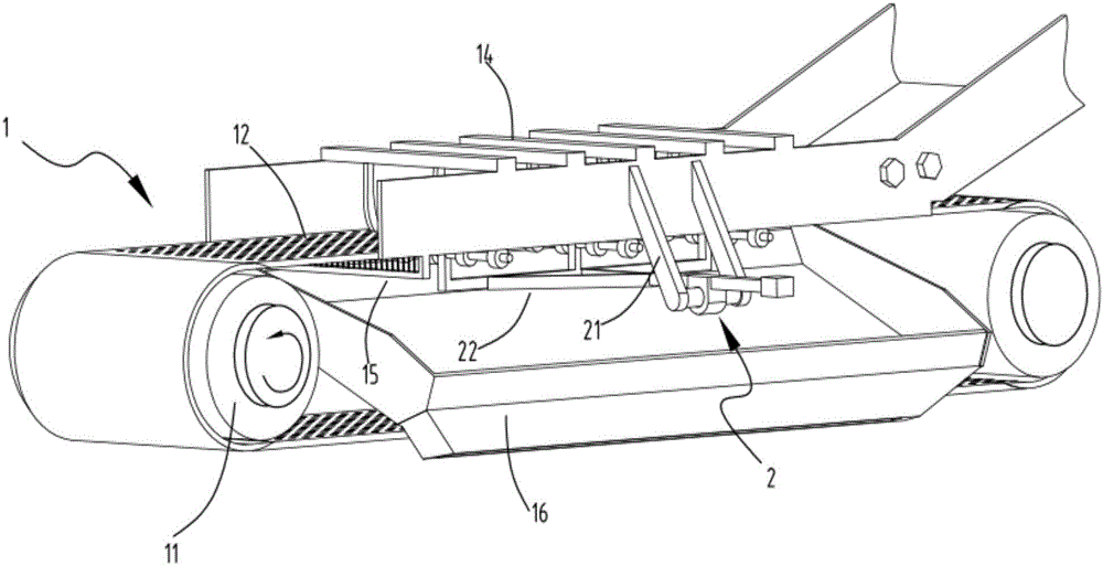
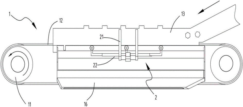
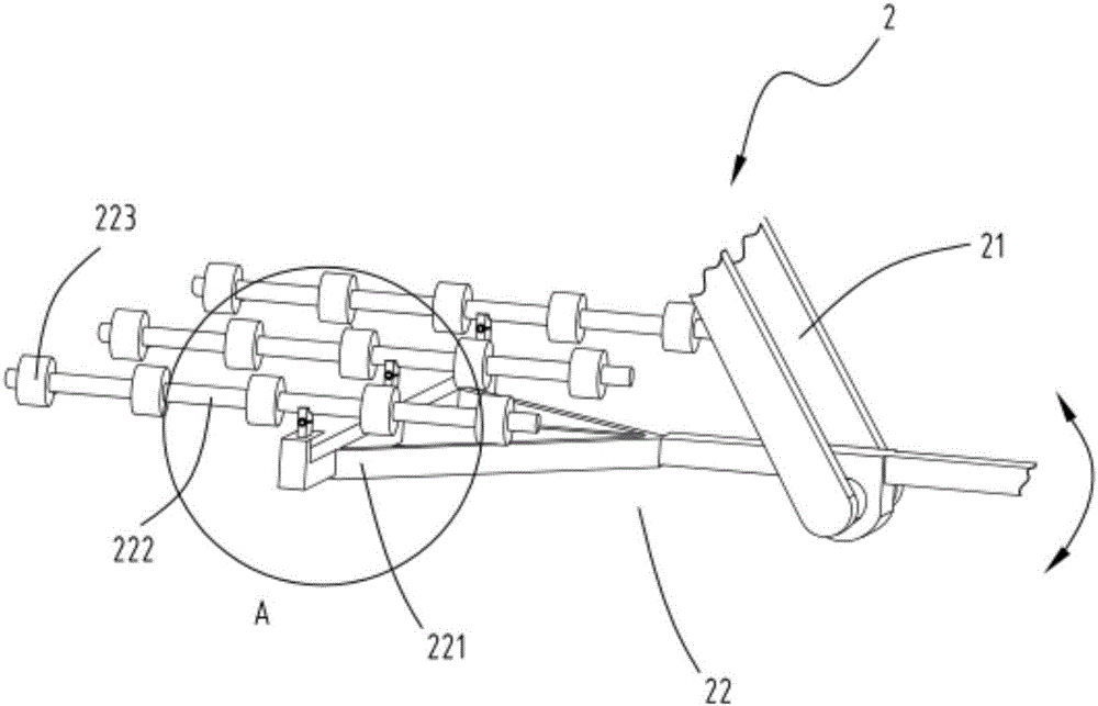
[0032] figure 1 It is a schematic structural diagram of a continuous separation device, figure 2 It is a schematic front view of a continuous separation equipment, image 3 It is a schematic diagram of the structure of the dithering part, Figure 4 It is a partially enlarged schematic diagram of the shaking frame, Figure 5 is a schematic diagram of the structure of the transmission part, Figure 6 It is a partially enlarged schematic diagram of the feeding device, Figure 7 It is a schematic diagram of the structure of the scraping device. Such as figure 1 , figure 2 , image 3 , Figure 4 , Figure 5 , Figure 6 and Figure 7 Shown, a kind of continuous separation equipment comprises transmission part 1, and this transmission part 1 comprises power unit 11, and the conveyer belt 12 driven by power unit 11, is provided with blanking hole 121 on described conveyer belt 12; Part 2, the shaking part 2 is arranged under the conveyor belt 12, the shaking part 2 is us...

Embodiment 2

[0043] Such as figure 1 , figure 2 , image 3 , Figure 4 , Figure 5 , Figure 6 and Figure 7 As shown, the components that are the same as or corresponding to those in the first embodiment are marked with the corresponding reference numerals in the first embodiment. For the sake of simplicity, only the differences from the first embodiment will be described below. The difference between the second embodiment and the first embodiment is: further, the bottom of the conveyor belt 12 and the rear end of the shaking frame 221 are provided with a scraping device 15 for removing the material in the blanking hole 121. The device 15 includes a fixed frame 151 and a brush bar 152 arranged on the fixed frame 151 ; the fixed frame 151 is arranged in an L shape, and the brush bar 152 is detachably arranged on the fixed frame 151 .

[0044]The setting of the scraping device 15 enables the powder that may remain in the discharge hole 121 to be promptly removed and dropped into the ...


PUM


Abstract

The invention relates to a continuous separation device, which comprises a transmission part, the transmission part includes a power device, and a conveyor belt driven by the power device, and a material drop hole is opened on the conveyor belt; a shaking part, the shaking part is arranged on Below the conveyor belt, the shaking part is used to shake the conveyor belt to separate the material powder on the conveyor belt and output it in different directions. The shaking part includes a rotating seat and a shaking device rotatably arranged on the rotating seat; Separation while transmission, continuous work and easy clogging of the filter screen affect the quality of the feed.

Description

technical field [0001] The invention relates to the technical field of separation equipment, in particular to a continuous separation equipment. Background technique [0002] At present, there are many shortcomings and deficiencies in the planned breeding of rabbits. The traditional breeding method generally adds feed directly to the feeding pan, but the feed processed now is mainly pellet feed, but there will be a lot of powder feed mixed in the pellet feed. Powder feed is not only It will affect the eating of rabbits, and it is not easy to clean up after accumulation. At the same time, the accumulated powder feed is easy to deteriorate and produce bacteria, which affects the breeding environment. [0003] The authorized announcement number is CN205436258U. A Chinese patent discloses a continuous separation device. By setting a movable filter screen, the outside of the movable filter screen is provided with a screen fixing plate, an inner rubber ring for retaining materials...

Claims


Application Information

Patent Timeline
Patent Type & Authority Applications(China)
IPC IPC(8): B07B1/10B07B1/42B07B1/52A23N17/00
CPCB07B1/10A23N17/00B07B1/42B07B1/522
Inventor 金勤生朱卫民
Owner 浙江众鑫新材料科技有限公司
Why Eureka
Try Eureka