Building pipe cutting clamp

A technology for pipes and construction, applied in the field of construction pipe cutting fixtures, can solve the problems of looseness, can not meet the requirements of use, easy to damage the pipes to be cut, etc., achieve good buffering and anti-slip effects, convenient cutting work, and avoid being clamped.

Inactive Publication Date: 2017-06-13
CHONGQING HAOLONG MACHINERY CO LTD
View PDF0 Cites 16 Cited by
  • Summary
  • Abstract
  • Description
  • Claims
  • Application Information

AI Technical Summary

Problems solved by technology

[0002] At present, in pipe processing, the clamps of wire cutting machines all use one type of clamp for one specification. The lower end uses a fixed clamp block, and the upper end uses a cylinder to control the movable clamp block. The clamping force remains constant and the reciprocating cycle increases with the use time The clamping force will gradually change and become loose. It is inconvenient to control the position of the pipe to be cut, and the operator cannot grasp the pressure on the pipe to be cut. It is easy to damage the pipe to be cut, and the pipe to be cut cannot be in an optimal position. people's requirements

Method used


Image

  • Building pipe cutting clamp

Examples


Embodiment Construction

[0010] The following will clearly and completely describe the technical solutions in the embodiments of the present invention with reference to the accompanying drawings in the embodiments of the present invention. Obviously, the described embodiments are only some, not all, embodiments of the present invention. Based on the embodiments of the present invention, all other embodiments obtained by persons of ordinary skill in the art without making creative efforts belong to the protection scope of the present invention.

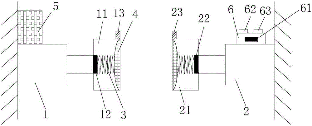
[0011] see figure 1 , the present invention provides a technical solution: a construction pipe cutting jig, including a first telescopic rod 1 and a second telescopic rod 2, the first telescopic rod 1 and the second telescopic rod 2 are oppositely arranged, realizing two directions The function of adjusting the position of the pipe to be cut can better fix the pipe to be cut. The inner ends of the first telescopic rod 1 and the second telescopic rod 2 are resp...


PUM


Abstract

The invention discloses a fixture for cutting construction pipes, which comprises a first telescopic rod and a second telescopic rod, and the inner ends of the first telescopic rod and the second telescopic rod are respectively provided with a first clamping block and a second clamping block. block, the connection between the first clamping block and the first telescopic rod is provided with a first pressure sensor, the connection between the second clamping block and the second telescopic rod is provided with a second pressure sensor, and the first A first infrared sensor and a second infrared sensor are respectively installed on the inside of the top of the clamping block and the second clamping block, and a control box is provided on the upper surface of the second telescopic rod. The building pipe cutting jig can automatically adjust the work of the first telescopic rod and the second telescopic rod, not only can fix the pipe to be cut, but also can prevent the pipe to be cut from being clamped, and can adjust the position and pressure of the pipe to be cut It is displayed, which brings convenience to the cutting work of building pipes.

Description

technical field [0001] The invention relates to the technical field of pipe cutting, in particular to a construction pipe cutting jig. Background technique [0002] At present, in pipe processing, the clamps of wire cutting machines all use one type of clamp for one specification. The lower end uses a fixed clamp block, and the upper end uses a cylinder to control the movable clamp block. The clamping force remains constant and the reciprocating cycle increases with the use time The clamping force will gradually change and become loose. It is inconvenient to control the position of the pipe to be cut, and the operator cannot grasp the pressure on the pipe to be cut. It is easy to damage the pipe to be cut, and the pipe to be cut cannot be in an optimal position. people's usage requirements. Contents of the invention [0003] The object of the present invention is to provide a construction pipe cutting jig to solve the problems raised in the above-mentioned background tech...

Claims


Application Information

Patent Timeline
Patent Type & Authority Applications(China)
IPC IPC(8): B23H11/00B23H7/02
CPCB23H11/003B23H7/02
Inventor 何德生
Owner CHONGQING HAOLONG MACHINERY CO LTD
Why Eureka
Try Eureka