
Processing equipment integrally formed with steel coil protective ring

A technology for processing equipment and steel coils, applied to other manufacturing equipment/tools, manufacturing tools, etc., can solve the problems of high production cost, low labor efficiency, slow production speed, etc., and achieve cutting control difficulties, simple structure, and cutting operation convenient effect

Active Publication Date: 2017-05-24
苏州科弗曼机械有限公司
View PDF10 Cites 4 Cited by
  • Summary
  • Abstract
  • Description
  • Claims
  • Application Information

AI Technical Summary

Problems solved by technology

[0003] In the prior art, the production and processing process of the inner and outer retaining rings of the steel coil is to hoist the steel coil to the strip steel uncoiling unit, and form a section of steel strip after uncoiling, sizing and cutting, and then Sections of steel strips are moved to the bending machine and folded into a 90-degree right angle, and then hoisted to the position of the forming machine, wound and processed into a circular retaining ring. The disadvantages are: there are many manual production and transportation links, and there are hidden dangers in hoisting and transportation. , many staffing, low labor efficiency, large equipment energy consumption, high production cost, many manual single-machine operations, resulting in many defective products, large waste of materials, slow production speed, and low output, so a simple structure and simple operation is required. Retainer production equipment with less work steps and high production efficiency

Method used


Image

  • Processing equipment integrally formed with steel coil protective ring
  • Processing equipment integrally formed with steel coil protective ring
  • Processing equipment integrally formed with steel coil protective ring

Examples


specific Embodiment approach

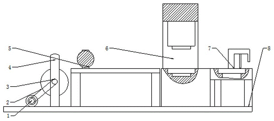
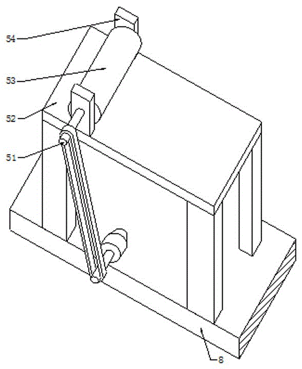
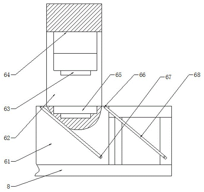
[0028] The specific embodiment: when the operator uses it, according to the size of the retainer to be processed, the corresponding size of the die 65 and the punch 63 are installed, and then the steel coil is installed on the steel coil rotating shaft 3, and the connection with the steel coil rotating shaft 3 is connected. The power supply of motor 1, the operation of motor 1 drives the steel coil rotating shaft 3 to rotate, thereby drives the steel coil to rotate, and then makes the steel strip contact with the flat plate 52 and moves forward, the operator connects the power supply of the motor 1 connected with the rotating shaft 51, The operation of the motor 1 drives the rotating shaft one 51 to rotate, and then drives the roller 53 to rotate. After the steel strip moves between the roller 53 and the flat plate 52, it moves forward under the friction between the roller 53. This design is uncoiling and discharging Provides convenience, simple structure, will not damage the s...


PUM


Abstract

The invention provides processing equipment integrally formed with a steel coil protective ring. The processing equipment comprises a support I, a rotary shaft I, a roller, a supporting base, a stamping device, a convex mould, a concave mould, a supporting plate, a lifting shaft, a beam, a rotary shaft, a connecting plate and a cutter, wherein the roller is fixedly arranged on the rotary shaft I; and the rotary shaft I is mounted at the upper end of the support I. According to the processing equipment provided by the invention, convenience is provided for uncoiling discharging, the convex mould is mounted at the lower end of the stamping device, and the concave mould is embedded into the center position at the upper end of the supporting base, so that the problems such as a complex structure, difficult operation and high cost of a forming device in the prior art are solved; the lifting shaft is mounted at the upper end of the supporting plate, the right end of the beam is fixedly arranged at the upper end of the lifting shaft, the left end of the beam is connected with the rotary shaft, the connecting plate is welded at the lower end of the rotary shaft, and the cutter is mounted at the lower end of the connecting plate, so that the problem that cutting control is difficult in the prior art is solved. The processing equipment is convenient to use, is convenient to operate, is simple in structure, can realize disposable stamping forming and is low in cost.

Description

technical field [0001] The invention relates to a processing device for integrally forming a steel coil retainer, which belongs to the field of mechanical equipment. Background technique [0002] In order to avoid scratches on the surface of the steel coil during transportation and storage, it is necessary to expose the outer surface of the steel coil for packaging protection, especially the corners of the inner and outer rings of the steel coil to protect the inner and outer layers of the steel coil The edge part of the product is called the inner and outer retainer of the steel coil. [0003] In the prior art, the production and processing process of the inner and outer retaining rings of the steel coil is to hoist the steel coil to the strip steel uncoiling unit, and form a section of steel strip after uncoiling, sizing and cutting, and then Sections of steel strips are moved to the bending machine and folded into a 90-degree right angle, and then hoisted to the position...

Claims


Application Information

Patent Timeline
IPC IPC(8): B23P23/04
CPCB23P23/04
Inventor 蒋伟
Owner 苏州科弗曼机械有限公司
Learn More